MANUAL | QUICK START GUIDE
ClubSport Pedals V3 Brake Performance Kit
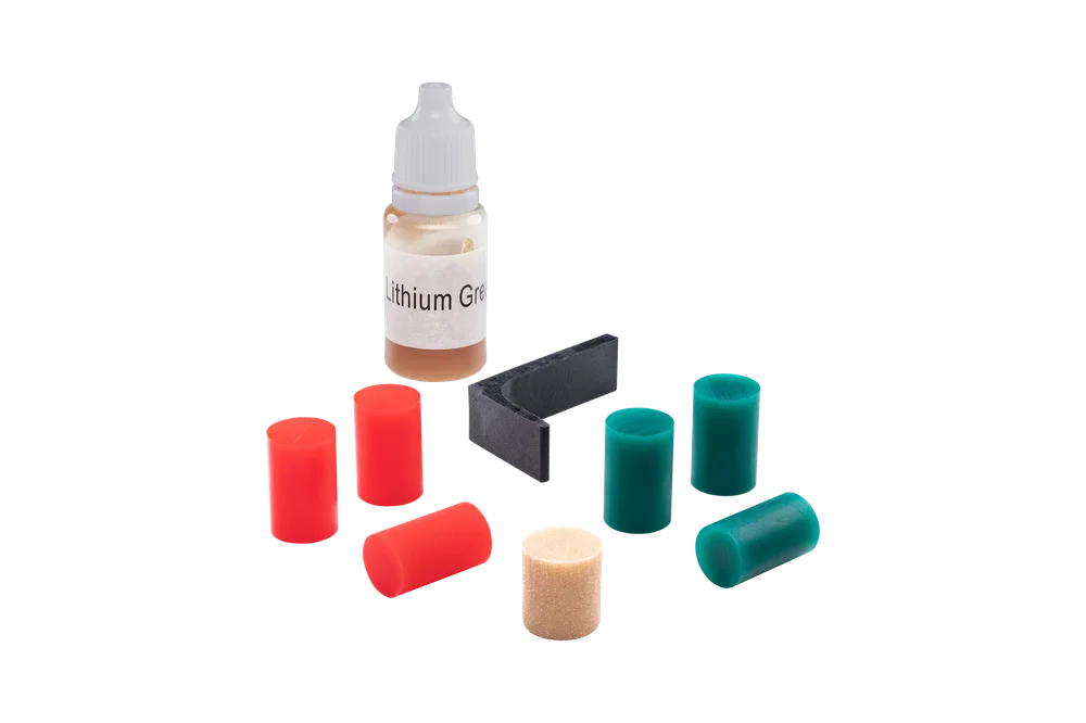
PACKAGE CONTENT
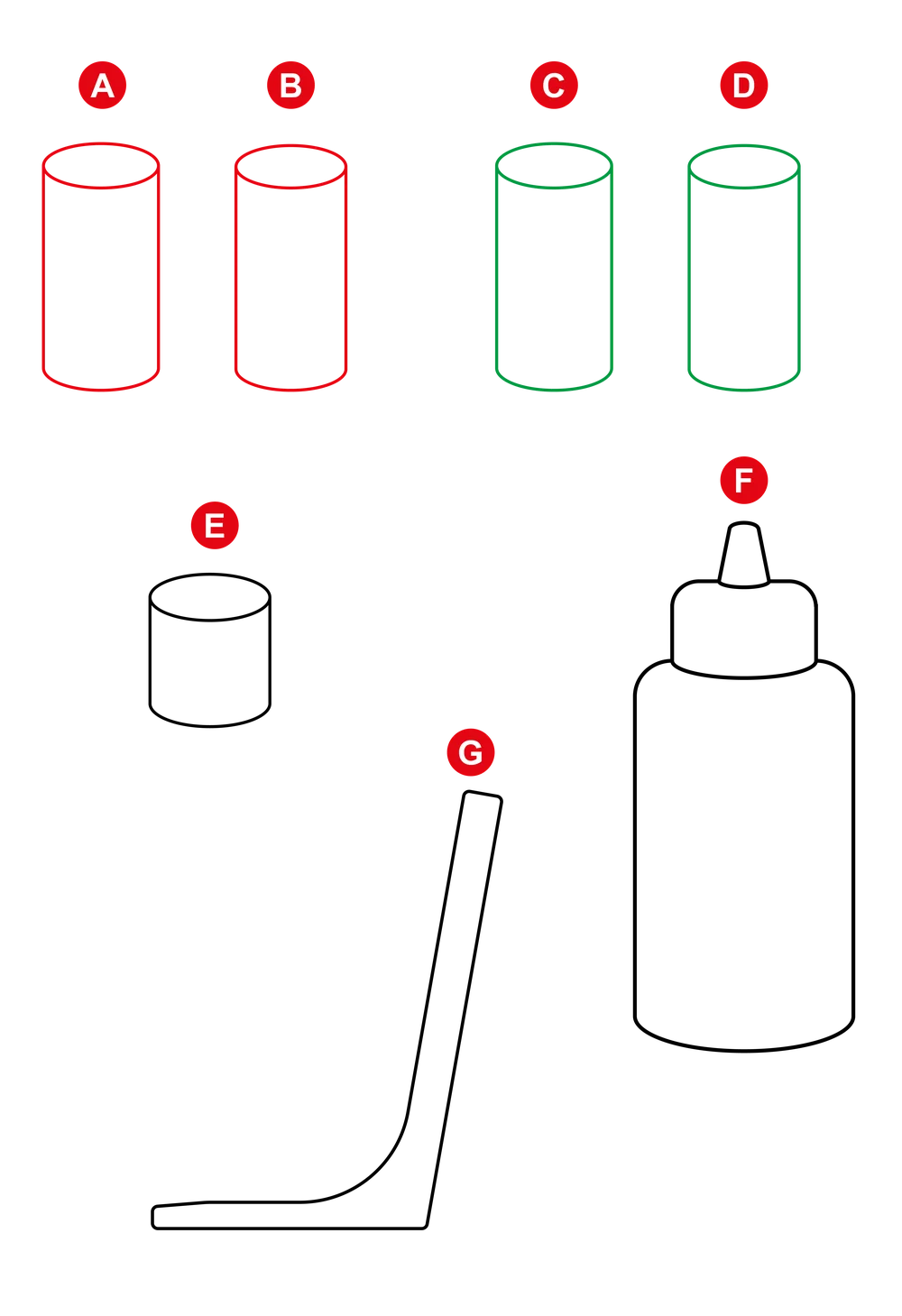
A - 2x Elastomer spring red Ø13 x 20 mm
B - 1x Elastomer spring red Ø12 x 20 mm
C - 2x Elastomer spring green Ø13 x 20 mm
D - 1x Elastomer spring green Ø12 x 20 mm
E - 1x Polyurethane spring (PU foam) Ø13,5 x 15 mm
F - 1x Lithium grease
G - 1x Installation tool (Fix-1)
NOTE: Required tools are not included in package content.
HARDNESS COMPARISON
There are many possible combinations of Elastomer springs (A) – (D). This comparison table may give you a better idea of the effects when combining the different Elastomer springs:
 |
 |
 |
 |
|
Ø13 Ø13 |
Ø13 Ø13 |
Ø13 Ø13 |
Ø12 Ø12 |
|
Very Hard |
Hard | Medium | Soft |
NOTE: Use a combination of any two Elastomer springs with the same diameter to achieve the desired level of hardness.
NOTE: Do not use a combination of two Elastomer springs with different diameters.
ASSEMBLY
IMPORTANT: Please follow these steps carefully to avoid damages due to assembly mistakes which cannot be covered by warranty.
STEP 1: Turn the brake preload screw to backside end position (lowest preload).

STEP 2: To avoid pinching the vibration motor cable, insert the included installation tool (Fix-1) ‘behind’ the brake assembly.
Place the tool to the side of the small grub screw, avoiding interference with the motor cable.
This tool should only be used to retain a gap between the brake assembly and pedal arm during the disassembly and assembly process.

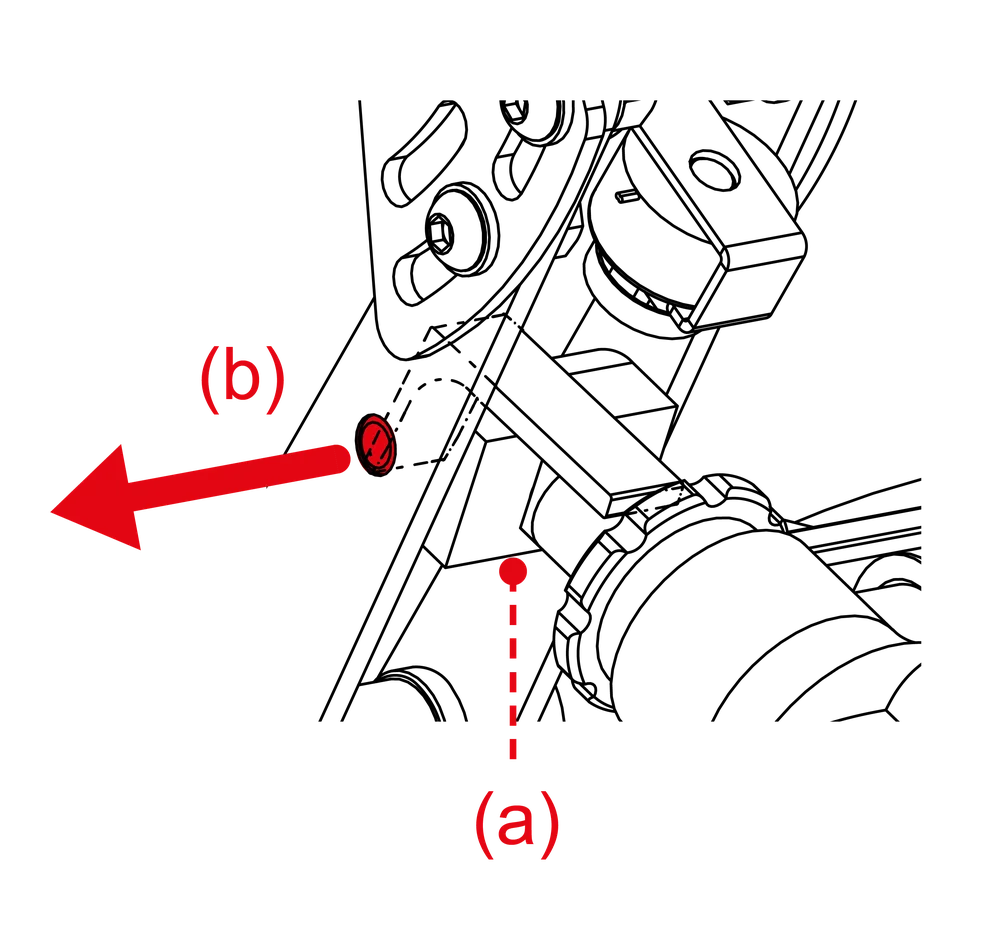
STEP 3: Loosen the small screw (a) with Allen Key 2.5 mm, then remove the thin bolt (b) from the brake pedal lever.
STEP 4: Disconnect the loadcell cable from ‘Brake’ port at the mainboard and take it out of the cable clips. Then turn the brake assembly downwards out from the brake pedal lever.

STEP 5: Remove the brake pedal bolt.

STEP 6: Remove the original Polyurethane springs and store them safely and light-protected for later use.

STEP 7: Insert the small Polyurethane spring (E) from Brake Performance Kit package content into the preload screw.

STEP 8: Select two pieces of the Elastomer springs (A) – (D) from Brake Performance Kit package content according to your preferences (refer to ‘hardness comparison’ of this Quick Strart Guide) and apply Lithium grease (F) to their surface.

STEP 9: Insert the selected two pieces of the Elastomer springs (A) – (D) into the preload screw.

STEP 10: Insert the brake pedal bolt into the preload screw.

STEP 11: Turn back the brake assembly into the brake pedal lever (using the installation tool again), then reconnect the loadcell cable to the ‘Brake’ port.
IMPORTANT: Take care of the cables to avoid damages!

STEP 12: Insert the thin bolt (a) into the brake pedal lever through the black block at the brake bolt, then tighten the small screw (b) with Allen Key 2.5 mm with moderate force again.

STEP 13: Adjust the preload screw so that the scale is within the correct use range and there is no mechanical play in brake pedal.
Note: Preload screw cannot be used in the full range as before, its use is limited only to eliminate the mechanical play:

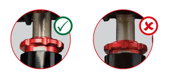
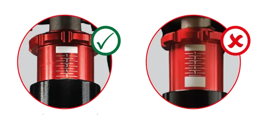
Minimum preload setting for brake pedal
Maximum preload setting for brake pedal
VIDEO GUIDE
The product warranty is provided by CORSAIR MEMORY, Inc. Refer to the terms & conditions of CORSAIR MEMORY, Inc. on fanatec.com