MANUAL | QUICK START GUIDE
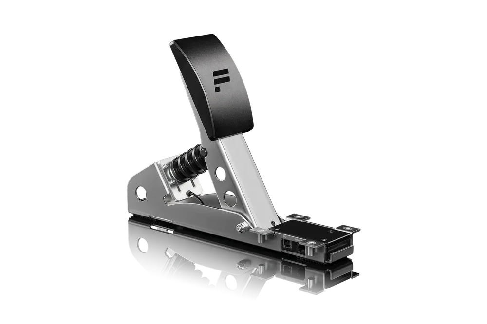
CSL Pedals Load Cell Kit
Manual
To get the most out of your CSL Pedals, please read this manual before first use. It contains important health and safety information and should be retained for future reference.
Index
1. General
2. Compatibility
3. Package Contents
4. Assembly
4.1 Plan Your Setup
4.2 Attachment
4.3 Pedal Plate Adjustment
4.4 Connections
4.5 Tuning Options
5. Cleaning
6. Troubleshooting
7. Video Guide
WARNING!
Photosensitive Seizures
A small percentage of people may experience a seizure when exposed to certain visual images, including flashing lights or patterns that may appear in video games. Even people who have no history of seizures or epilepsy may have an undiagnosed condition that can cause these “photosensitive epileptic seizures” while watching video games. These seizures may have a variety of symptoms, including light-headedness, altered vision, eye or face twitching, jerking or shaking of arms or legs, disorientation, confusion, or momentary loss of awareness. Seizures may also cause loss of consciousness or convulsions that can lead to injury from falling down or striking nearby objects. Immediately stop playing and consult a doctor if you experience any of these symptoms. Parents should watch for or ask their children about the above symptoms – children and teenagers are more likely than adults to experience these seizures. The risk of photosensitive epileptic seizures may be reduced by taking the following precautions:
• Sit farther from the TV screen.
• Use a smaller TV screen.
• Play in a well-lit room.
• Do not play when you are drowsy or fatigued.
If you or any of your relatives have a history of seizures or epilepsy, consult a doctor before playing.
WARNING!
Musculoskeletal disorders
Use of game controllers, keyboards, mice, or other electronic input devices may be linked to serious injuries or disorders. When playing video games, as with many activities, you may experience occasional discomfort in your hands, arms, shoulders, neck, or other parts of your body. However, if you experience symptoms such as persistent or recurring discomfort, pain, throbbing, aching, tingling, numbness, burning sensation, or stiffness, DO NOT IGNORE THESE WARNING SIGNS. PROMPTLY SEE A QUALIFIED HEALTH PROFESSIONAL, even if symptoms occur when you are not playing a video game. Symptoms such as these can be associated with painful and sometimes permanently disabling injuries or disorders of the nerves, muscles, tendons, blood vessels, and other parts of the body. These musculoskeletal disorders (MSDs) include carpal tunnel syndrome, tendonitis, tenosynovitis, vibration syndromes, and other conditions.
While researchers are not yet able to answer many questions about MSDs, there is general agreement that many factors may be linked to their occurrence, including medical and physical conditions, stress and how one copes with it, overall health, and how a person positions and uses their body during work and other activities (including playing a video game). Some studies suggest that the amount of time a person performs an activity may also be a factor. If you have questions about how your own lifestyle, activities, or medical or physical condition may be related to MSDs, see a qualified health professional.
PACKAGE CONTENTS
1. GENERAL
ATTENTION!
• The device must not be exposed to rain or humidity in order to avoid risk of fire and / or electric shock.
• Operating room temperature: 15°C - 35°C
• Excessive use may cause health risks. We recommend taking a 5 minute break after every 20 minutes of use. Do not drive for more than 2 hours per day.
• We strongly advise you to not drive a vehicle immediately after using a video game.
• In case of interference with other wireless 2.4 GHz devices, the interfering devices must be removed or switched off.
• Not intended for children under the age of 6 years old. Contains small pieces which pose a choking hazard!
• Do not open the casing of the device.
• This device contains components that cannot be repaired by the user, opening will void the warranty.
WARNING!
The CSL Pedals Load Cell Kit must be connected to the appropriate wheel base port or PC USB port.
• If the CSL Pedals Load Cell Kit becomes damaged in any way, stop usage immediately and contact Fanatec® Customer Support: https://help.fanatec.com/hc/en-us
• All specifications in this document are subject to change. The PC driver may be updated to implement new features or general improvements.
• This manual discusses assembly, connections, and functions related to Fanatec® devices and other additional devices. This is not a replacement manual for the other corresponding products! Read the quick guides or user manuals for the other products!
• The warranty does not include defects that are due to commercial use of the product. See chapter “Warranty” at the end of this user manual as well as the Terms & Conditions on Fanatec.com for more details.
2. COMPATIBILITY
The CSL Pedals can be used with all CSL, CSL Elite, ClubSport, and Podium series wheel bases as well as standalone on a PC via the ClubSport USB Adapter.
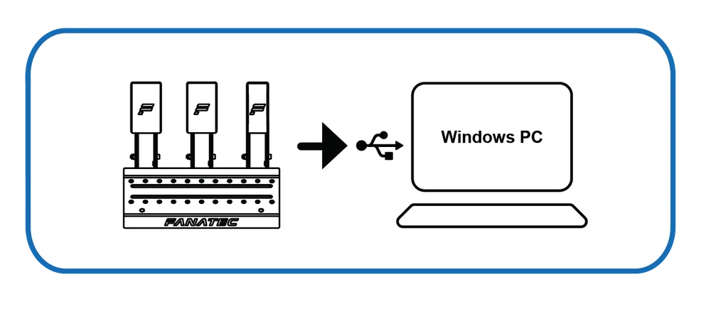
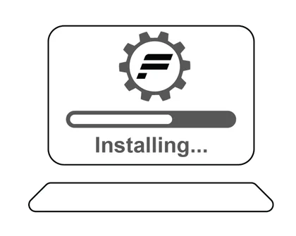
IMPORTANT: We always recommend updating your Fanatec® devices to the latest firmware versions. A Windows PC is required to perform firmware updates. Download the latest PC driver containing the latest firmwares.
Visit Fanatec.com/driver

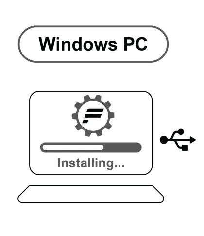
Windows PC

Update Firmware
3. PACKAGE CONTENTS
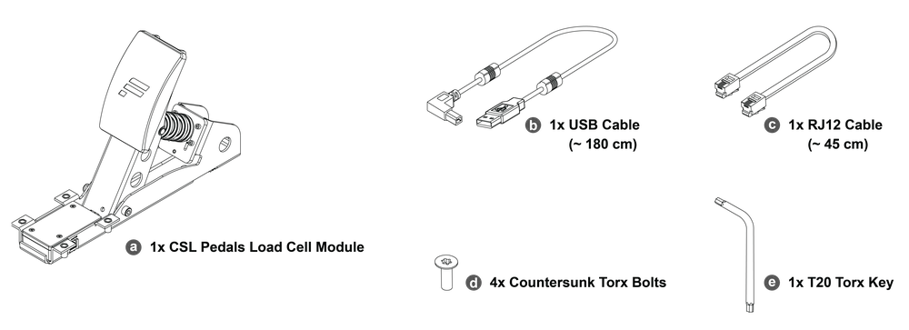
a - 1x CSL Pedals Load Cell Module
b - 1x USB Cable (~ 180 cm)
c - 1x RJ12 Cable (~ 45 cm)
d - 4x M4x12 mm Countersunk Mounting Bolts
e - 1x T20 Torx Key
4. ASSEMBLY
4.1 PLAN YOUR SETUP
To get started with using the CSL Pedals Load Cell Kit, decide on your preferred pedal module position, and pedal plate position. then connect the CSL Pedals Load Cell Kit to your wheel base via the included RJ12 cable or to a PC via USB. It is important to follow the chapter sequence of this manual for an effective assembly and setup procedure.
ATTENTION: See chapter 4.4 “Connections” for which pedal module must be connected to which port of the CSL Pedals Load Cell module. Only use the included USB and RJ12 cable from your CSL Pedals Load Cell Kit package contents to avoid damages!
ATTENTION: Rest the CSL Pedals Load Cell Kit box on its side in order to remove the contents without dropping any items and to avoid damages!

4.2 ATTACHMENT
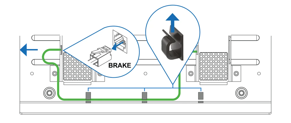
Remove the RJ12 cable of the standard brake module from the accelerator pedal module of your CSL Pedals and remove the cable from the cable management clips.
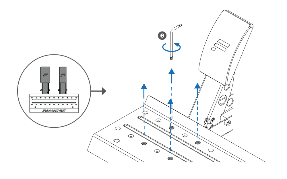
Remove the bolts of the brake and accelerator pedal units modules from the heel rest of your CSL Pedals using the included Torx key (e).
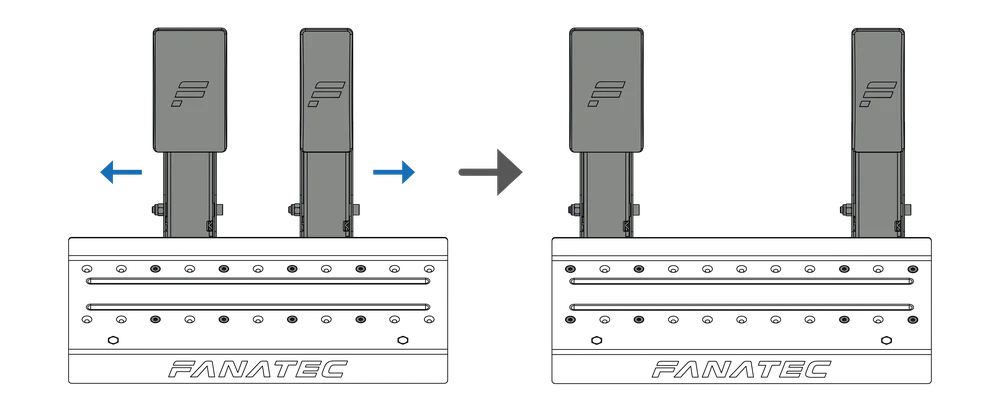
Move the brake and accelerator pedal modules outwards. (Exclude the standard brake module if you choose to not use the standard brake module as a clutch)
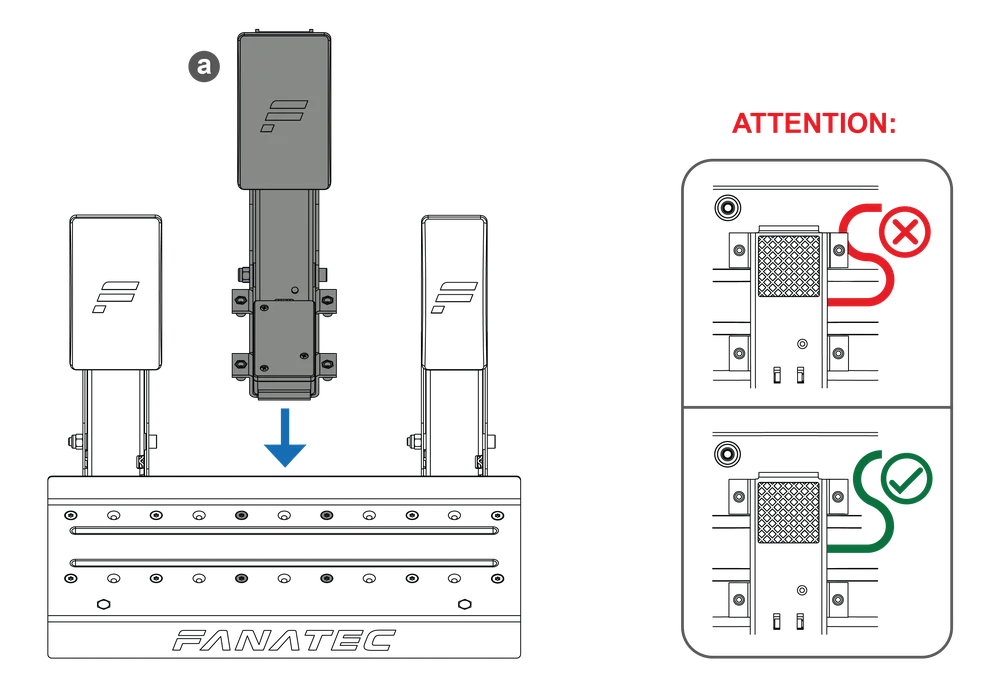
Place the CSL Pedals Load Cell Kit (a) module under the heel rest in your preferred position.
ATTENTION: Be careful not to pinch the pedal cable when placing the heel rest and attaching the pedal!
Insert the included bolts (d) of the CSL Pedals Load Cell Kit unit and the bolts of the brake and accelerator pedal modules, then firmly secure the pedal units to the heel rest using the included Torx key (e). (Exclude the standard brake if you choose to not use the standard brake as a clutch)
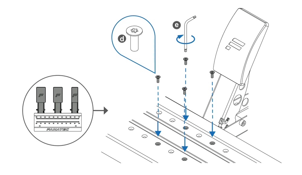
OPTIONAL STEP: Remove the foam insert from the standard brake module if you choose to use the standard brake as a clutch.
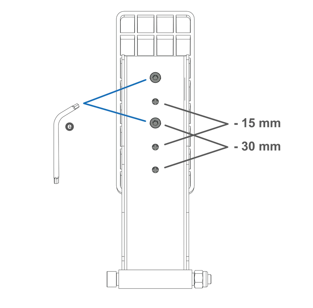
4.3 PEDAL PLATE ADJUSTMENT
The CSL Pedals Load Cell Kit module features a height-adjustable pedal plate. There are 3 height settings that can be adjusted in descending increments of 15 mm. Use the included T20 Torx key (e) to loosen the bolts in order to perform the adjustment.
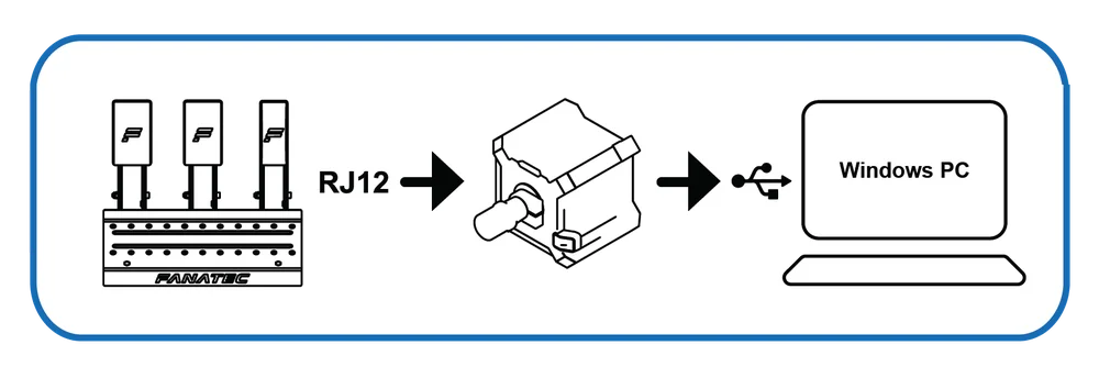
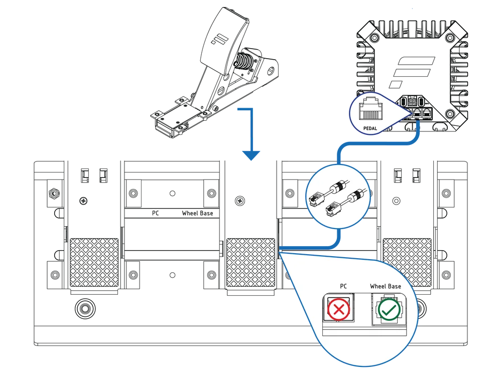
4.4 CONNECTIONS
Connect the included RJ12 cable c to the ‘Wheel Base / Load Cell’ port of the accelerator module and to the ‘Load Cell’ port of the CSL Pedals Load Cell module.
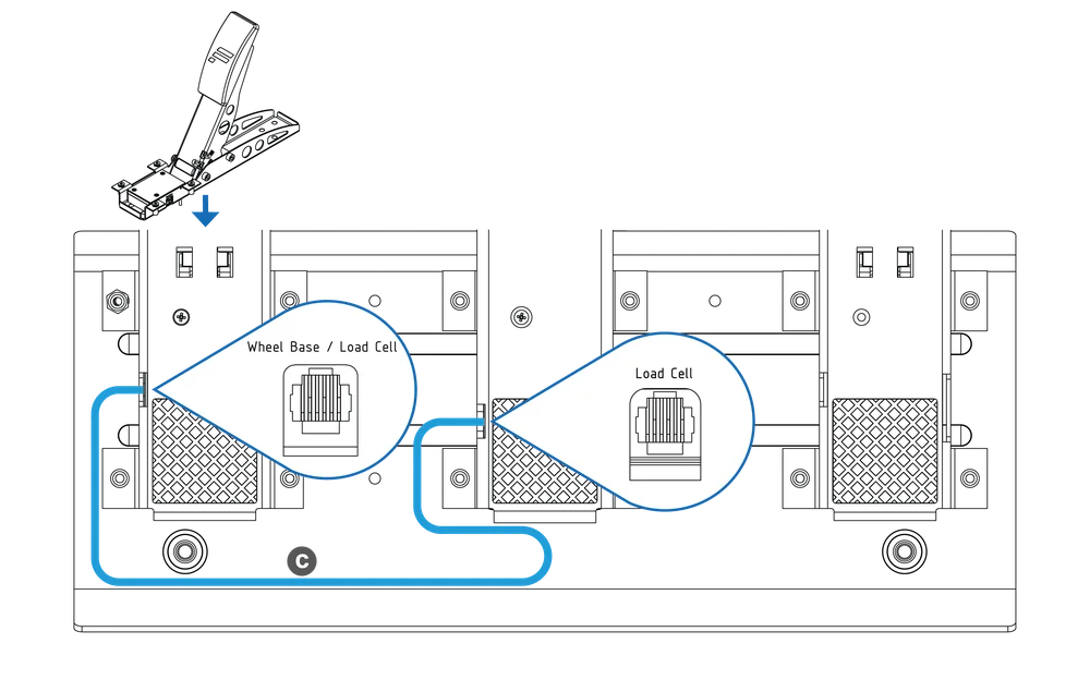
Connect the standard brake module cable to the ‘Clutch’ port of the accelerator module. (If you choose to use the standard brake module as a clutch)
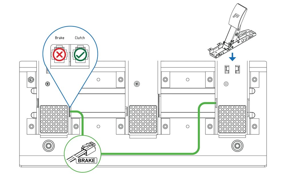
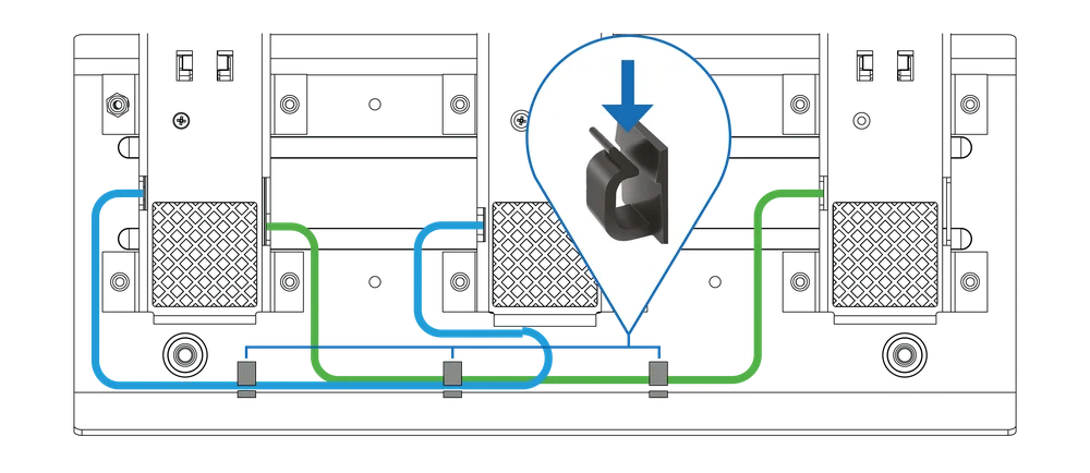
Insert the cables into the cable management clips
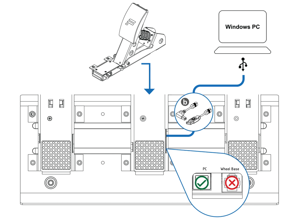
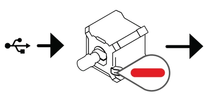
IMPORTANT! Do not connect the Pedals via RJ12 and USB at the same time!

OPTION 1
Connect the CSL Pedals Load Cell module to a Windows PC via the included USB cable b .
OPTION 2
Connect the CSL Pedals Load Cell module to a Fanatec wheel base via the RJ12 cable included with the standard CSL Pedals.
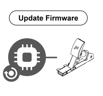
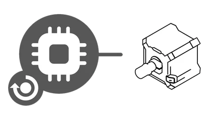
Update wheel base firmware
Windows PC
PC Mode
Update Firmware
4.5 TUNING OPTIONS
After installing the Fanatec PC Driver (Fanatec Control Panel) open the Fanatec Control Panel, then navigate to ‘Pedals’ as shown below:
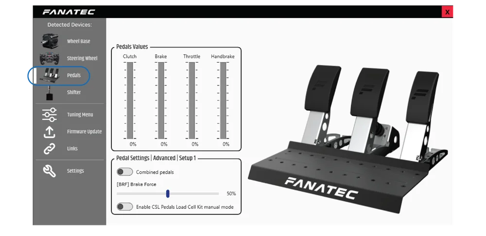
BRF (Brake Force)
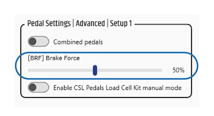

Brake Force changes the force needed to reach 100% brake input for load cell brake pedals and is available when a pedal set featuring a load cell brake is connected to a wheel base via RJ12 and to a PC via USB. ‘Lo’ requires the least amount of brake pressure, 100 requires the most amount of brake pressure. The default value is 050.
BRF can be accessed via the wheel base Tuning Menu as well.
Combined Pedals
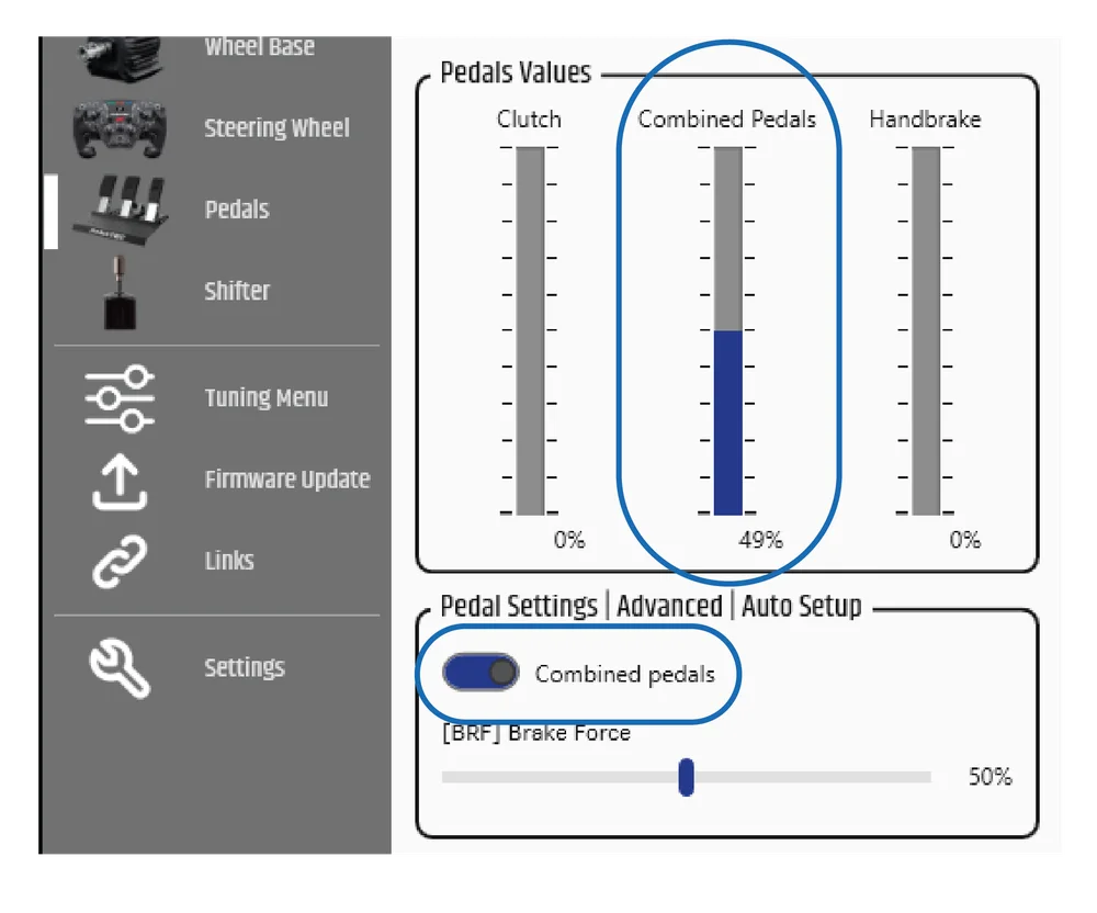
This feature allows the brake (load cell) and accelerator pedals to simultaneously operate on a single axis. 49% to 0% is operated by the brake pedal and 50% to 100% is operated by the accelerator pedal.
This feature’s purpose is to allow compatibility with older games that support only a single axis for braking and accelerating and is only accessible when connected to a Fanatec wheel base.
Manual Mode
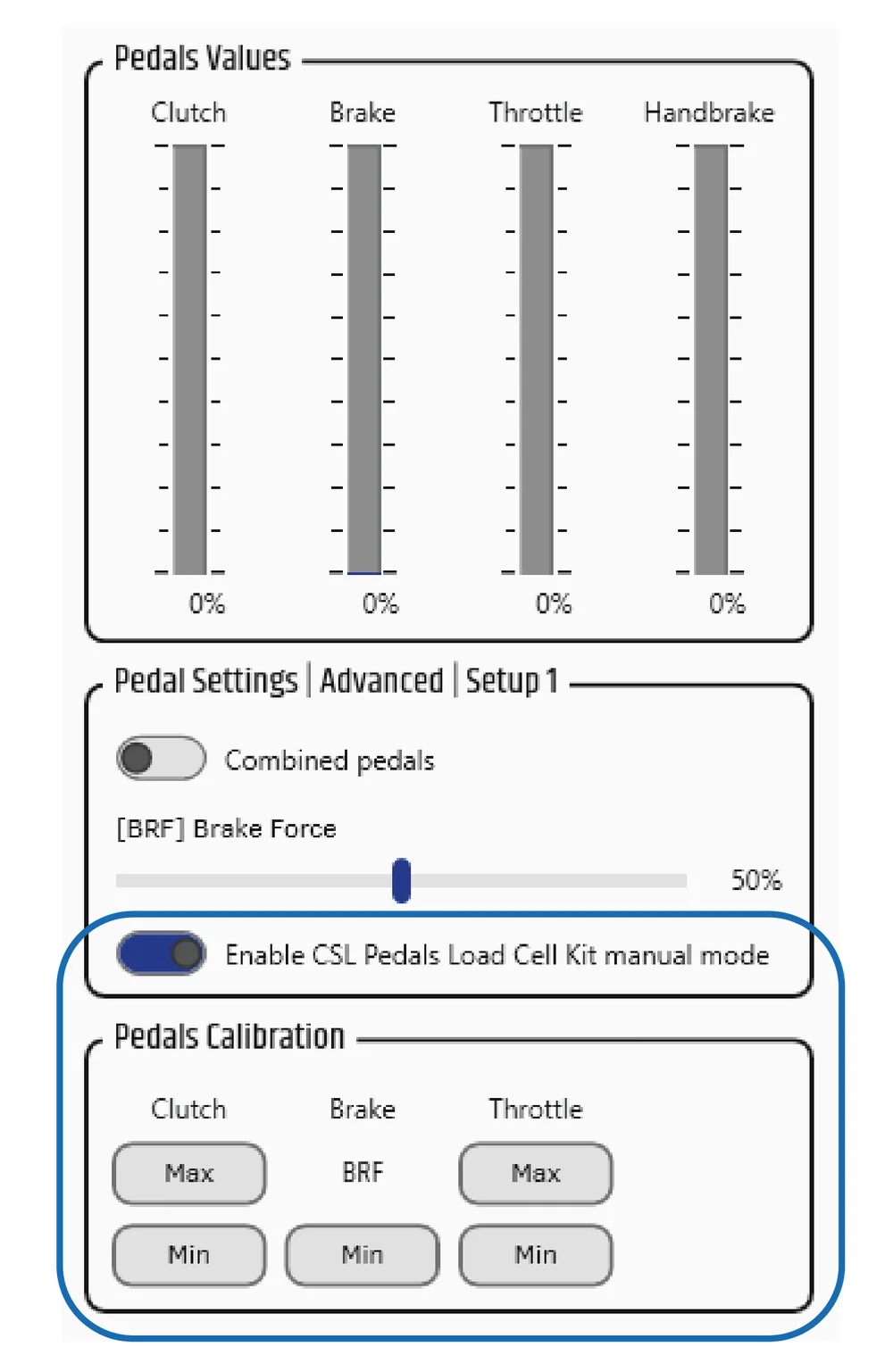
By enabling ‘...Manual Mode’, the minimum and maximum values of each pedal can be manually set throughout the mechanical travel range of each pedal.
Example: Press the clutch pedal to the desired lower travel range for when you want the signal to start, then select ‘Min’. Press the clutch pedal to the desired upper travel range for when you want the signal to reach 100%, then select ‘Max’.
BRF (Brake Force) acts as the maximum value setting for the load cell brake and is accessible via the wheel base Tuning Menu as well. The brake ‘Min’ and ‘Max’ / ‘Min’ options for the other pedals are only accessible via the Fanatec Control Panel.
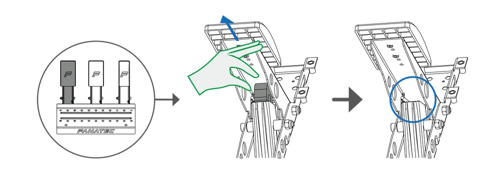
5. CLEANING
Clean only with a dry or slightly damp microfibre cloth. Using cleaning solutions may damage your CSL Pedals Load Cell Kit.
6. TROUBLESHOOTING
The CSL Pedals Load Cell Kit must not be modified in any way, other than what is explicitly described in this manual. Corsair Memory, Inc. expressly prohibits analysis and utilisation of the electronics, hardware, software, and firmware contained in this device. In case difficulties occur when using your CSL Pedals Load Cell Kit, please use the following troubleshooting guide. You will find further details and contact information on Fanatec.com/support/faq.
If the CSL Pedals Load Cell Kit is not working properly:
| Problem Description | Solution |
| The PC driver or the wheel base does not recognise the CSL Pedals Load Cell Kit. |
Make sure that you have updated your wheel base and CSL Pedals LC firmware to the latest firmware version contained within the latest PC driver which can be downloaded from fanatec.com/driver. |
| Ensure that you are using the RJ12 cable included with your CSL Pedals package. |
|
| Ensure that the RJ12 cables are plugged in the correct ports of the CSL Pedals Load Cell Kit module and the correct port of the wheel base. See section 4.4 “Connections” |
|
| After performing a firmware update of the CSL Pedals LC, the manually calibrated pedal positions are reset. |
After performing a firmware update of the CSL Pedals LC, the manually calibrated pedal positions have to be manually calibrated again. See section 4.5 “Tuning Options”, “Manual Mode” |
| Pedal signal of the CSL Pedals and / or CSL Pedals LC in-game behaviour feels incorrect. |
Connect the CSL Pedals LC to a PC or a wheel base. Start the Fanatec Control Panel and check the indicator bars of each pedal while pressing each corresponding pedal. You may need to do a manual calibration of minimum and / or maximum positions or reselect ‘...Manual Mode’ to adjust the pedal signal behaviour as desired. |
| After startup the CSL Pedals and / or CSL Pedals LC pedal signals are not correctly indicated, can be verified in the Fanatec Control Panel. |
When powering ON the CSL Pedals LC without ‘...Manual Mode’ selected, every pedal lever must first be pressed to the maximum position and then back to the minimum position. The signal of each pedal should be fine. See section 4.5 “Tuning Options”, “Manual Mode” |
| Your PC does not boot when the CSL Pedals LC is connected via USB before Windows has booted. |
This phenomenon is related to some main board manufacturers’ BIOS. In this case, it is required to boot the PC first and then connect the CSL Pedals LC via USB. |
| How can I get in contact with Fanatec customer support? |
There is a chat service on our website, or you can create a Support Ticket via the ‘My Products’ section of your Fanatec account. Fanatec.com |
7. VIDEO MANUAL
The product warranty is provided by CORSAIR MEMORY, Inc. Refer to the terms & conditions of CORSAIR MEMORY, Inc. on fanatec.com