MANUAL | QUICK START GUIDE
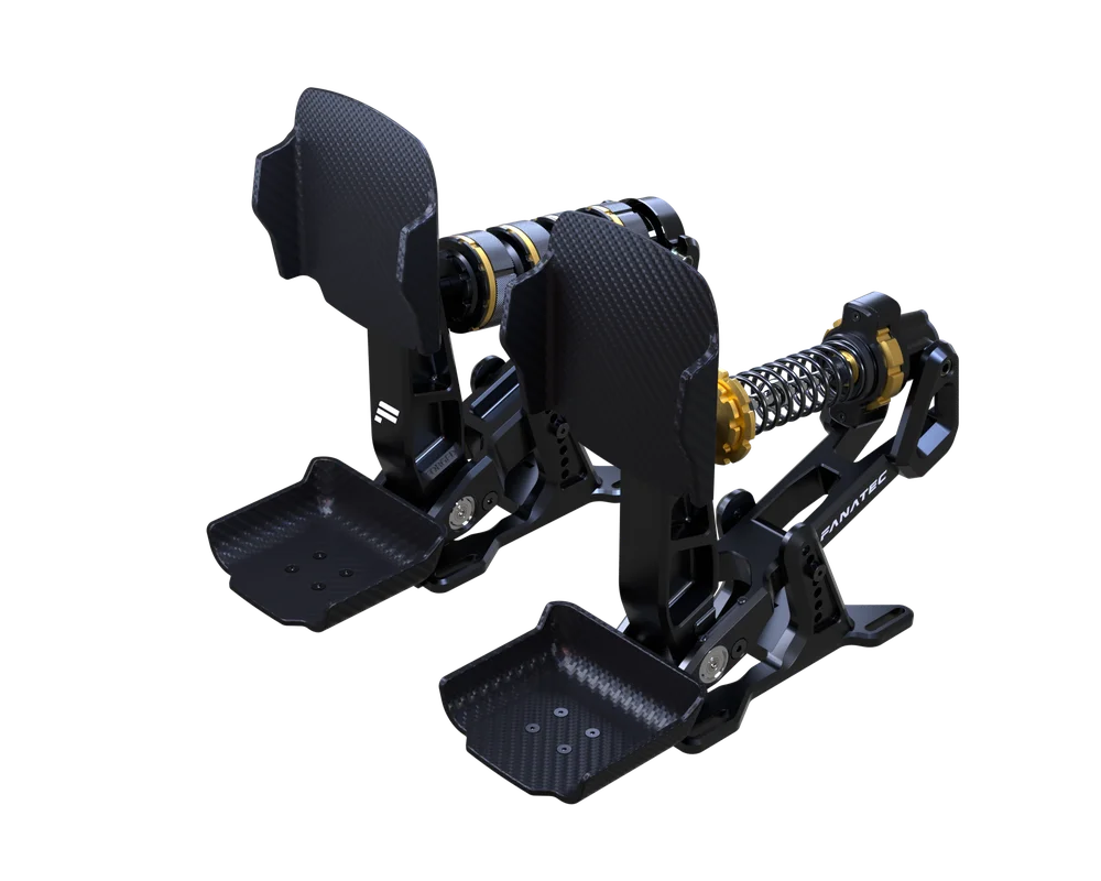
Podium Pedals Formula
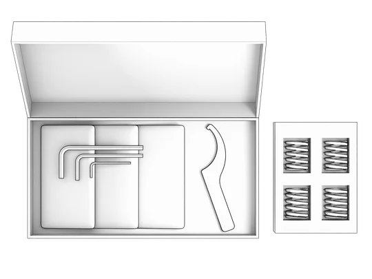
A - PACKAGE CONTENT
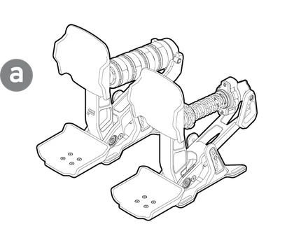
1x Podium Pedals Formula
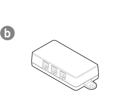
1x Connection Box
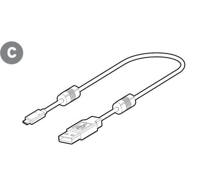
1x USB Cable
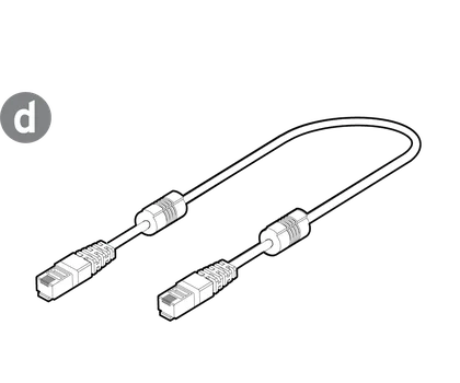
1x RJ12 to RJ11 Cable (RJ12 to Base, RJ11 to Pedals)

1x 5 mm Allen Key

1x 4 mm Allen Key

1x 2.5 mm Allen Key
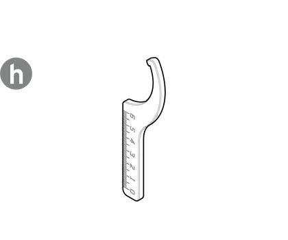
2x Cup Assist Tools
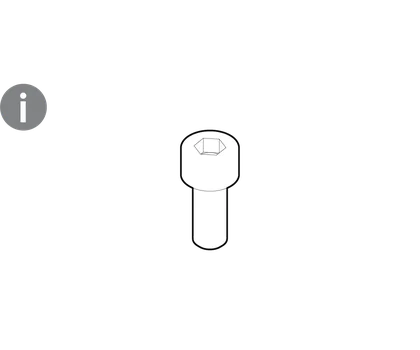
8x M6 Bolts

8x M6 Washers
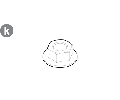
8x M6 Flange Nuts
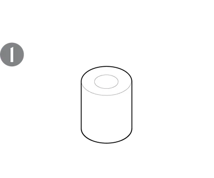
4x Brake Elastomers
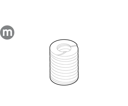
4x Brake Springs
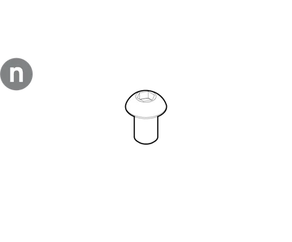
2x M3 Bolts
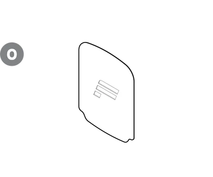
2x Grip Stickers

1x Safety & Compliance Leaflet

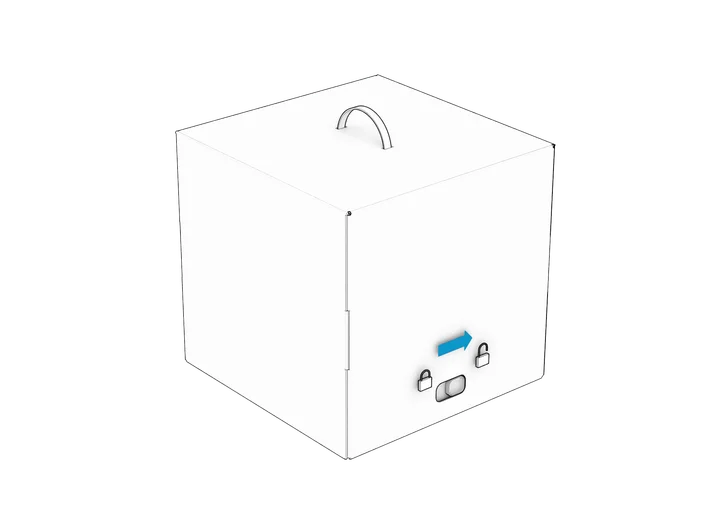
B - UNBOXING
STEP 1
Move the lock tab to the unlock symbol as indicated.
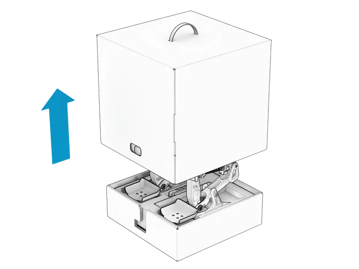
STEP 2
Lift the top lid slowly to reveal the pedals.
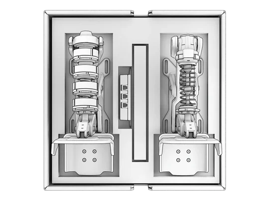
STEP 3
Remove the contents and prepare for the assembly procedure.
C - HARD-MOUNTING
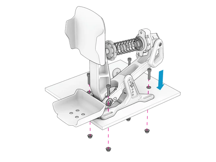
C1 - GENERIC PEDAL DECK
Align each pedal module with the prepared mounting holes, then hard-mount using parts (i), (j), (k), and the included Allen key (e).
|
CAUTION: Only mount the pedal modules to a solid metallic plate. Any other material such as wood or plastic may result in damage to the product.
|
|
NOTE: 13mm wrench required to tighten up the hard-mount. Not included. |
|
TIP: Use the provided Drilling Template if needed. |
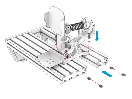
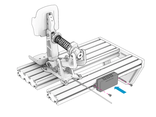
C2 - ALUMINUM PROFILE
STEP 1
Align each pedal module with the slots and T-nuts, then hard-mount using parts (i), (j), and the included Allen key (e).
|
NOTE: M6 T-nuts are required for mounting to aluminum profile extrusions. Not included. |
|
CAUTION: Ensure that the cables of each pedal module is not pinched before mounting. |
STEP 2
Mount the connection box (b) using the M3 bolts (n) and the included Allen key (f). in an accessible position close to the pedals, ensuring the cables are not under tension.
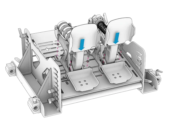
C3 - CLUBSPORT GT COCKPIT
STEP 1
Place the pedal modules in your desired positions, then hard-mount using parts (i), (j), (k), and the included Allen key (e).
|
CAUTION: Ensure that the cable of each pedal module is not pinched before mounting. |
|
NOTE: The ClubSport GT Cockpit pedal deck allows the pedal modules to be mounted in all practical positions. 13mm wrench required to tighten up the hard-mount. Not included.
|
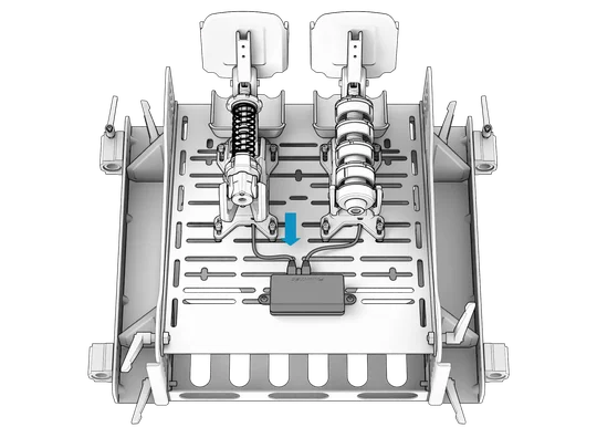
STEP 2
Mount the connection box (b) using the M3 bolts (n) and the included Allen key (f) to the approximate area indicated below, ensuring the cables are not under tension.
| NOTE: The throttle and clutch cables will cross over if the connection box is mounted with the ports facing rearward (right image). |
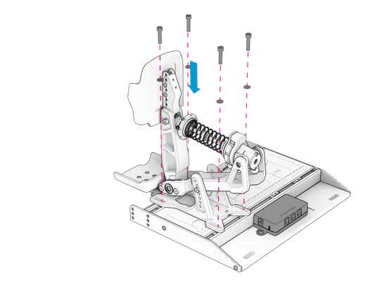
C4 - PODIUM PEDALS MOUNTING PLATE & HEEL REST
STEP 1
Mount the Mounting Plate to any metallic pedal deck, aluminum profile extrusion, or compatible Fanatec cockpit using the bolts, washers, and nuts which are included with the Mounting Plate.
|
CAUTION: Only mount the Mounting Plate to a solid metallic plate. Any other material such as wood or plastic may result in damage to the product. |
|
NOTE: 13mm wrench required to tighten up the hard-mount. Not included. |
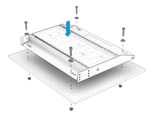
|
NOTE: There is no need to mount the heel rest to the Mounting Plate unless you plan to use the Podium Pedals Formula without the pre-installed heel cups. If you plan to use the heel rest, refer to section "HEEL CUPS" for intsructions on how to remove the heel cups completely.
|
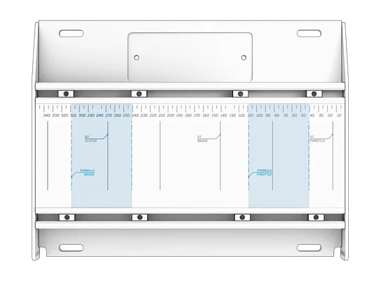
STEP 2
Position the preinstalled T-nuts in the approximate positions where the pedal modules will be mounted.
|
TIP: The alignment guides on the Mounting Plate surface provide the optimal mounting positions. |
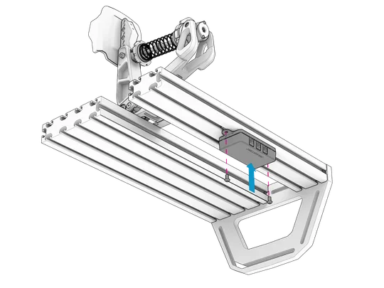
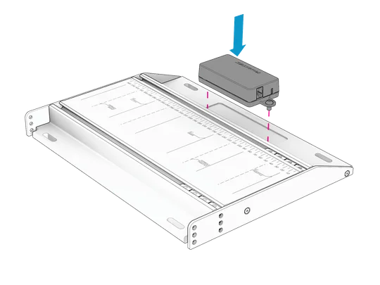
STEP 3
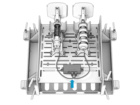
Attach the connection box (b) using the M3 bolts (n) and the included Allen key (f) to the Mounting Plate with the ports facing rearwards.
STEP 4
Mount each pedal module in the desired position using parts (i), (j), and the included Allen key (e).
|
CAUTION: Ensure that the cable of each pedal module is not pinched before mounting. |
D - CONNECTIONS
STEP 1
Connect each pedal module cable to the correct port.
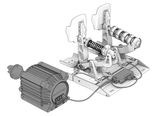
STEP 2
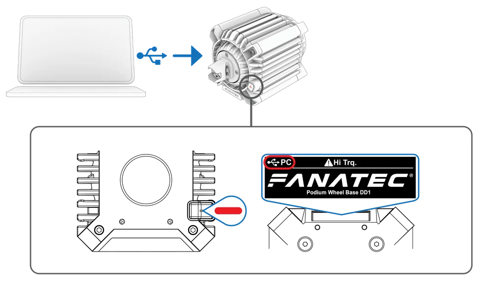
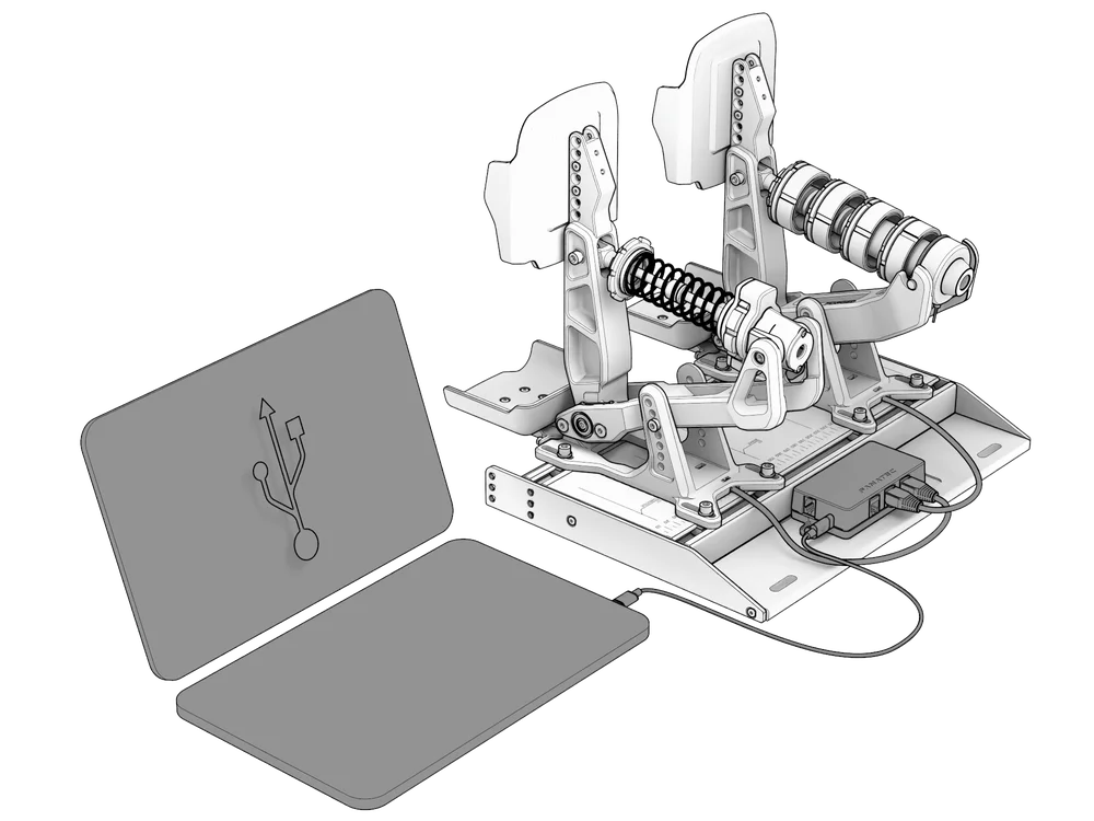
Connect the connection box to either a Fanatec Base or Windows PC via the included cables (c) and (d).
|
CAUTION: Cable (d) is RJ12 to RJ11. The RJ12 connector plugs into your Fanatec Base and the RJ11 connector plugs into the connection box (b). Forcing the incorrect connector into the incorrect port may result in damage. |
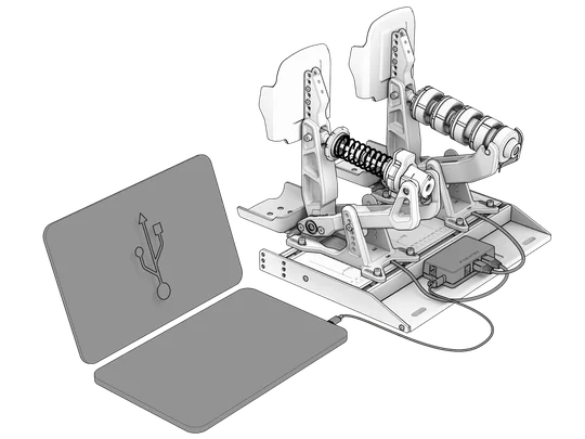
| TIP: Console users can connect the pedals via RJ12 to a Fanatec Base and via USB to a Windows PC at the same time. The pedals will prioritize the Base connection. If you wish to adjust pedal curves via the Fanatec App on PC, you can power off your Base. The pedals will automatically switch the connection to your PC and you can adjust your curves. Once saved to the pedals' memory, power on your Base again and the connection will switch back to your Base from which you can select the newly configured curves. |
E - FIRMWARE UPDATE
|
NOTE: A Base firmware update may be needed for your Fanatec Podium Pedals to be detected properly. We recommend checking regularly for new updates. Firmware updates can only be performed with the Fanatec App (PC only). |
STEP 1
Download and install the latest version of the Fanatec App.

STEP 2
To update your Base, make sure it is connected to a Windows PC via USB and is in PC mode (red). Use the included USB cable with your Fanatec Base.
STEP 3
Connect the pedals to a Windows PC.
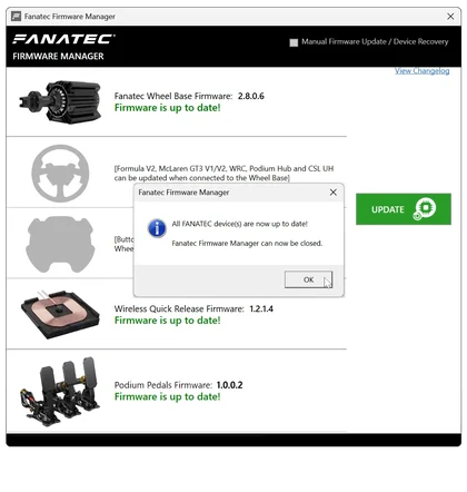
STEP 4
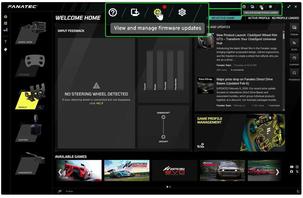
Open the Fanatec App. If new firmware is available, a red dot will be displayed next to the firmware icon. Click on the icon to open the Firmware Manager.
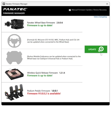
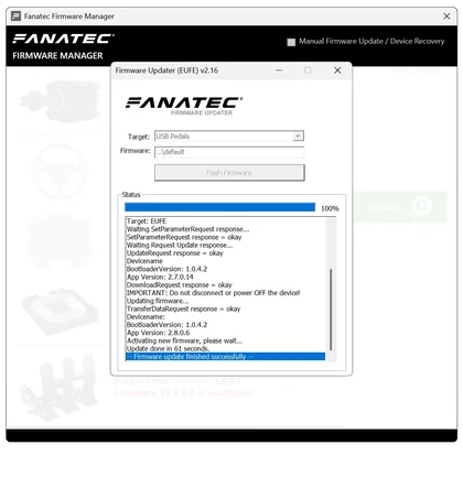
STEP 5
Click on the "UPDATE" button in the Firmware Manager. Follow the instructions on screen and update your hardware components. Close the Firmware Manager when all updates are completed.
F - PEDAL TUNING (HARDWARE)
GENERAL / ALL PEDALS
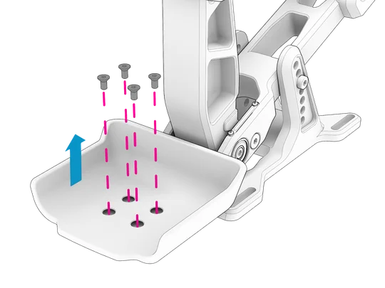
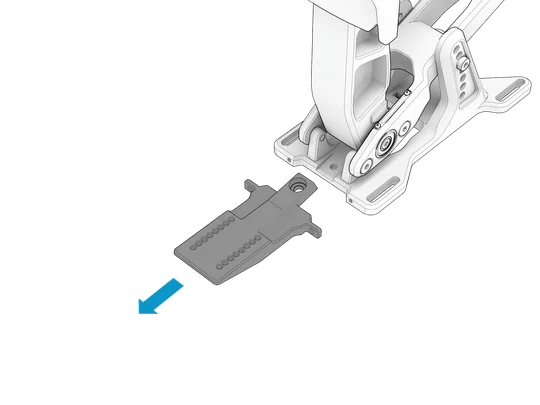
PEDAL PLATE ADJUSTMENT
STEP 1
Remove the 4 bolts holding the plate along the rear of the pedal arm using the included 2.5 mm Allen key (g).
| CAUTION: Do not use excessive force when loosening and tightening the bolts. There is a soft Threadlock applied to these bolts in production. Ensure that the included 2.5 mm Allen key is inserted correctly and apply steady torque when loosening. |
STEP 2
Select a higher or lower position as desired.
STEP 3
Re-insert and tighten the bolts.
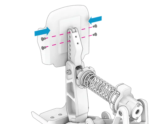
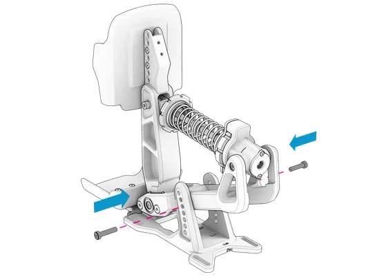
PEDAL ANGLE
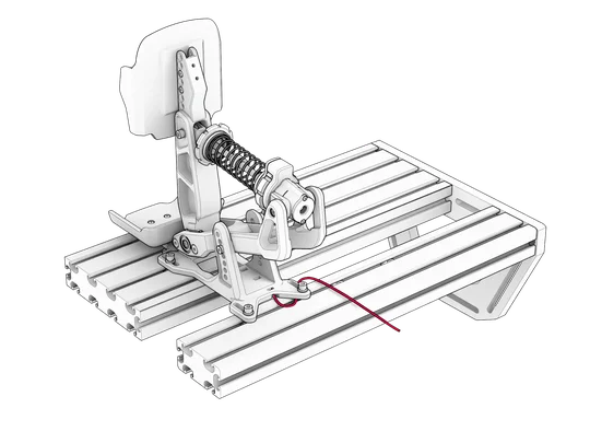
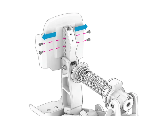
STEP 1
Remove the 2 bolts from the sides of the pedals module as illustrated below using the included Allen key (f).
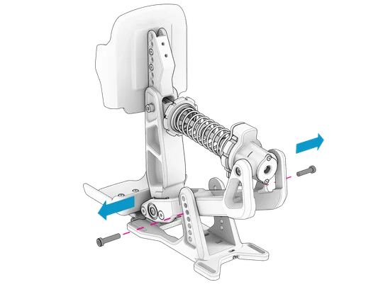
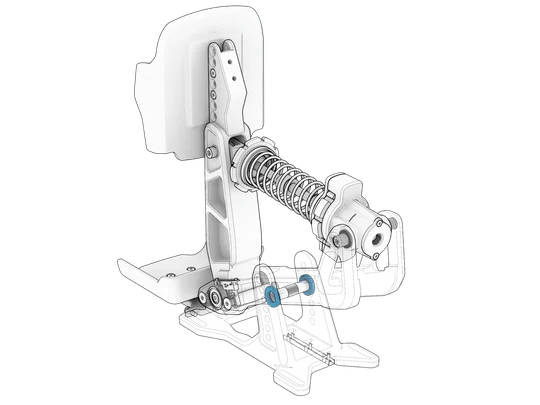
STEP 2
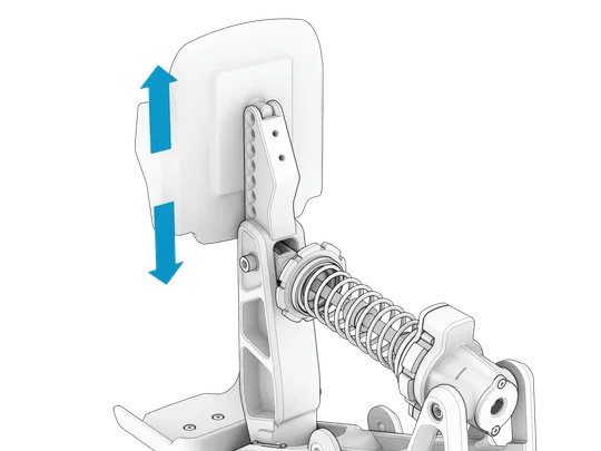
Adjust the angle of the pedal arm as desired.
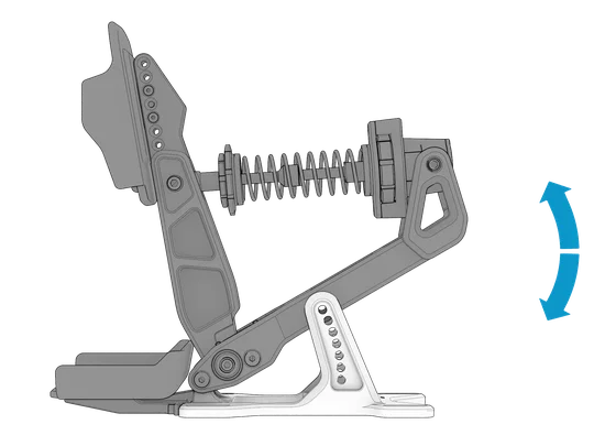
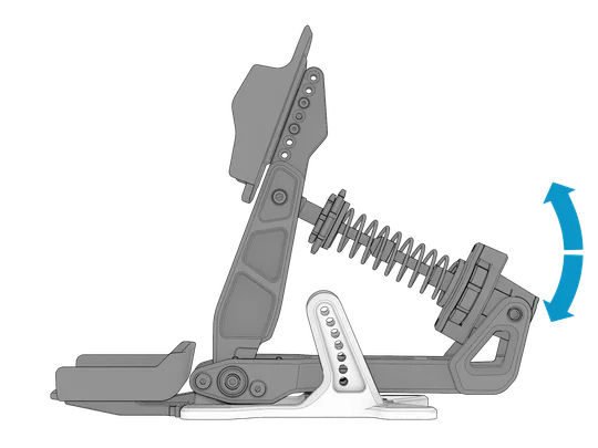
| TIP: The upper 2 positions are optimal for inverted mounting of each pedal module. |
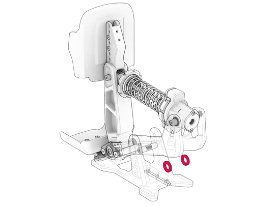
|
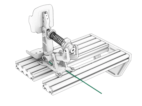
CAUTION: Before reinserting the bolts removed in STEP 1, ensure that the illustrated washers are present.
|
STEP 3
Reinserting the bolts removed in STEP 1 and firmly tighten using the included Allen key (f).
HEEL CUPS
STEP 1
Remove the heel cup bolts using the included Allen key (g).
STEP 2
Position the heel cup as desired within the mounting point range.
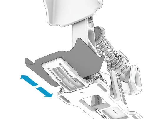
STEP 3
Reinsert the heel cup bolts and tighten firmly.
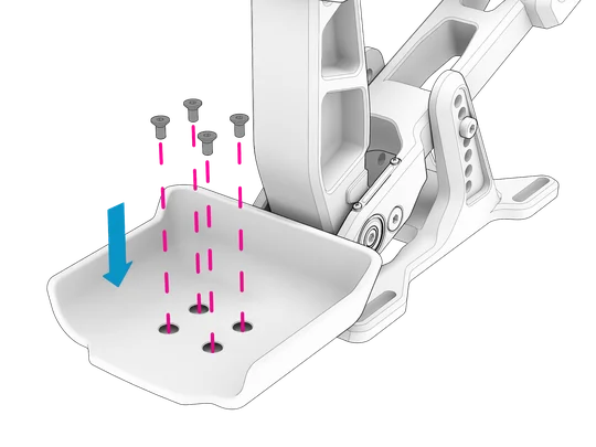
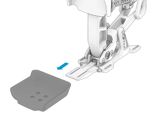
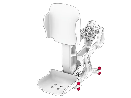
HEEL CUP AND BRACKET REMOVAL
STEP 1
Remove the heel cup bolts using the included Allen key (g) and remove the heel cup.
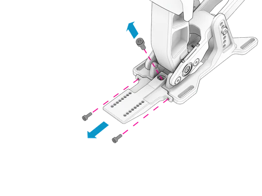
STEP 2
Remove the bigger center bolt with the included Allen key (e).
Remove the two smaller bolts using a 3 mm Allen key (not included).
GRIP STICKERS
| NOTE: The grip stickers offer additional grip for sim racers who prefer wearing shoes and not recommended for sim racers who prefer wearing socks or being barefoot. |
STEP 1
Remove the adhesive cover paper from the rear of the grip sticker (o).
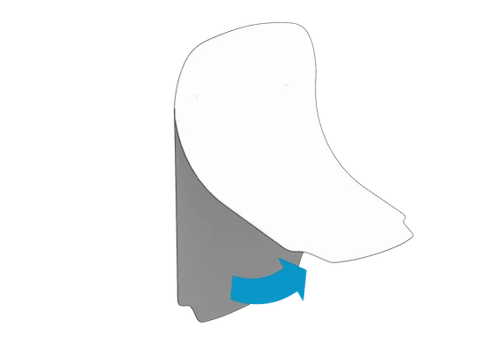
STEP 2
Apply the grip sticker to the pedal faceplate surface and press firmly across the entire sticker to ensure complete adhesive contact.
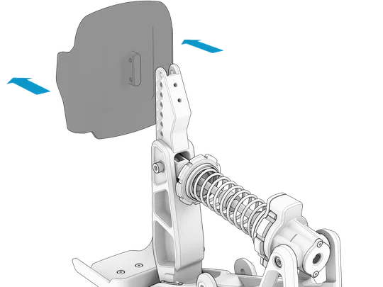
CHANGING THE PEDAL FACE PLATES
STEP 1
Remove the 4 bolts holding the plate along the rear of the pedal arm using the included 2.5 mm Allen key (g).
| CAUTION: Do not use excessive force when loosening and tightening the bolts. There is a soft Threadlock applied to these bolts in production. Ensure that the included 2.5 mm Allen key is inserted correctly and apply steady torque when loosening. |
STEP 2
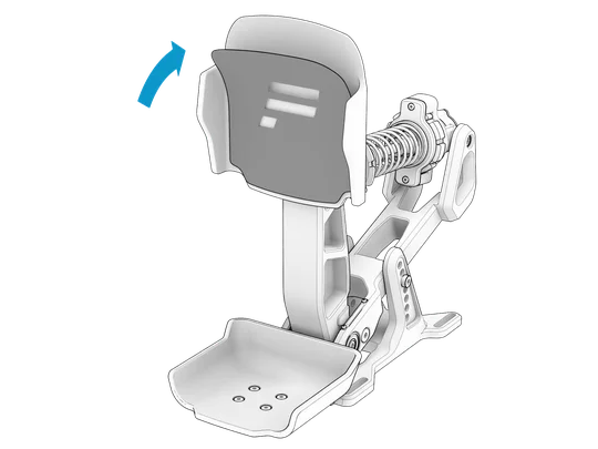
Remove the Formula pedal plate.
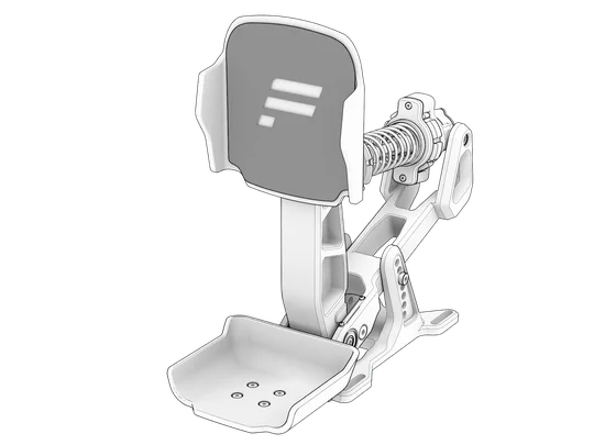
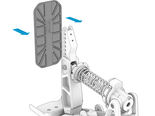
STEP 3
Align the GT pedal plate with the mounting holes of the pedal arm.
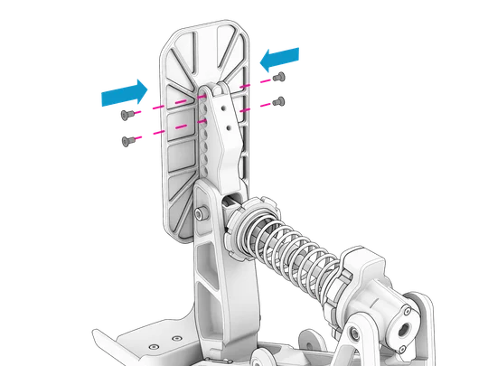
STEP 4
Re-insert and tighten the bolts.
THROTTLE
PRELOAD
STEP 1
Loosen the locking disc as much as possible to allow maximum movement of the preload adjustment disc.
STEP 2
Rotate the preload adjustment disc to achieve the desired preload level.
- CLOCKWISE: to DECREASE the preload.
- COUNTER-CLOCKWISE: to INCREASE the preload.
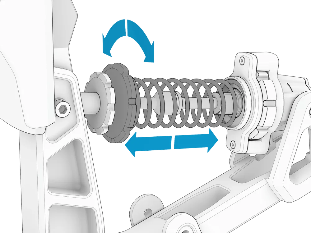
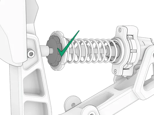
STEP 3
Tighten the locking disc to lock the preload adjustment disc in place.
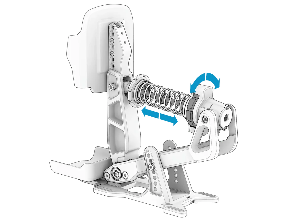
PEDAL TRAVEL
Rotate the travel adjustment disc to achieve the desired pedal travel distance.
- CLOCKWISE (-): to DECREASE the travel.
- COUNTER-CLOCKWISE (+): to INCREASE the travel.
BRAKE
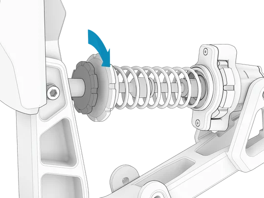
PRELOAD
Unlock the brake stack by loosening the locking disc, then rotate the preload adjustment cup as desired. When the desired adjustment has been made, lock the brake stack by tightening the locking disc.

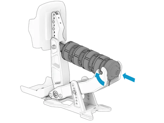
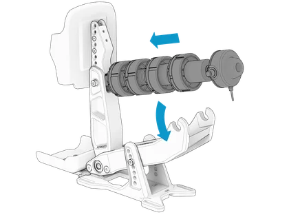
ELASTOMER / SPRING CHANGE
STEP 1
Loosen the locking disc and preload adjustment cup to the least preloaded state.

STEP 2
Push on the rear of the load cell unit to free the elastomer / spring stack studs from the notches on the pedal module body.
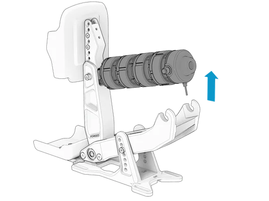
STEP 3
Remove all the stacked components to the furthest set of elastomer / springs you would like to change.
| TIP: The table below provides a guide for which elastomer / spring combinations provide different car type braking feels. |
| CAR | LOWER | HIGHER | ||||||
| ROAD | E | S | S | S | E | E | S | S |
| GT / RALLY | E | E | S | S | E | E | E | S |
|
PROTOTYPE / FORMULA |
E | E | E | S | E | E | E | E |
E = ELASTOMER
S = SPRING
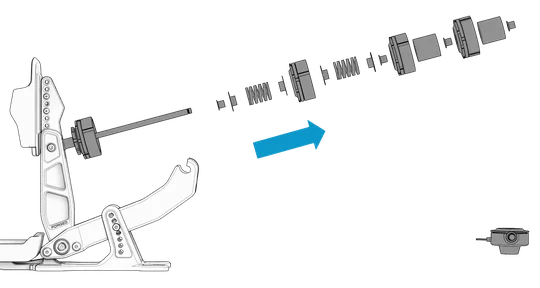
STEP 4
Restack the rod in the same order of components per set when reassembling the elastomer / spring stack with your selected elastomer / spring combination.
| CAUTION: Ensure that the plastic spring washers are installed for each spring used. |
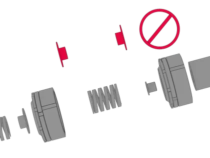
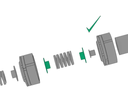
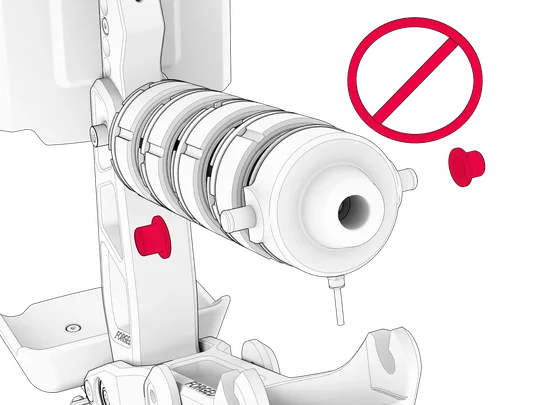
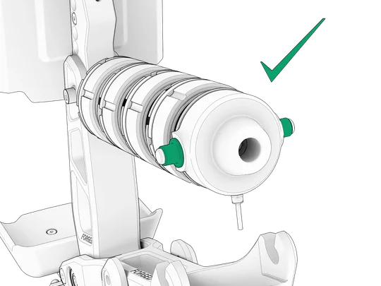
| CAUTION: Ensure the plastic caps are installed before reinserting the stack's studs into the notches on the pedal module. |
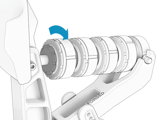
STEP 5
Tighten the preload adjustment cup to the desired preloaded state, then tighten the locking disc.
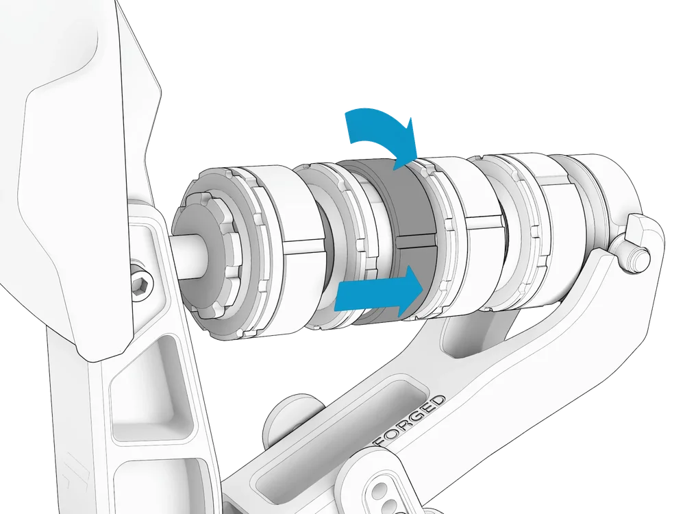
ELASTOMER COMPRESSION CONTROL SYSTEM
STEP 1
Rotate the compression control cups to achieve the desired level of elastomer / spring compression and lockout.
- CLOCKWISE: to DECREASE compression and INCREASE lockout.
- COUNTER-CLOCKWISE: to INCREASE compression and DECREASE lockout.
TIP:
|
STEP 2
Rotate the locking rings to secure the compression control cups once the desired adjustment has been made.
- CLOCKWISE: to LOCK.
- COUNTER-CLOCKWISE: to RELEASE.
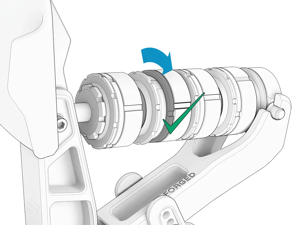
| CAUTION: Securing the compression control cups with the locking rings is essential for effective force transfer through the brake stack to the loadcell. |
| TIP: If the locking rings or compression control cups are stuck, use the included cup assist tools (h) to loosen the rings and cups effectively. |
G - PEDAL TUNING (FANATEC APP)
GENERAL
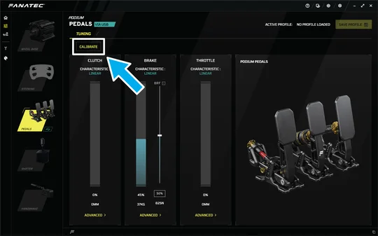
CALIBRATION
STEP 1
Click on the "CALIBRATION" button in the top left corner of the pedals input window.
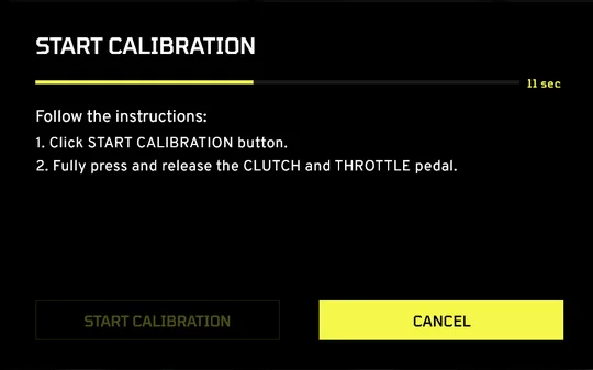
STEP 2
Follow the instructions on screen.
THROTTLE
| NOTE: Do not forget to click on "SAVE PERMANENTLY" to save your settings once complete. |
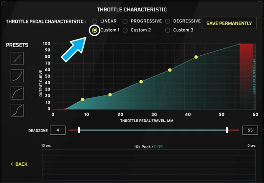
OUTPUT CURVE (PRESETS)
Select either "LINEAR", "PROGRESSIVE", or "DEGRESSIVE" for the simplest curve adjustment according to your preference.
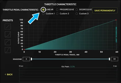
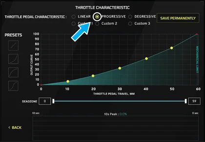
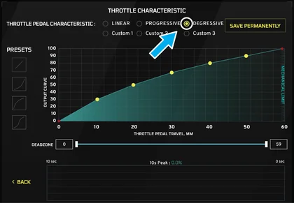
For more advanced curve adjustments, select a "PRESET" according to your preference.
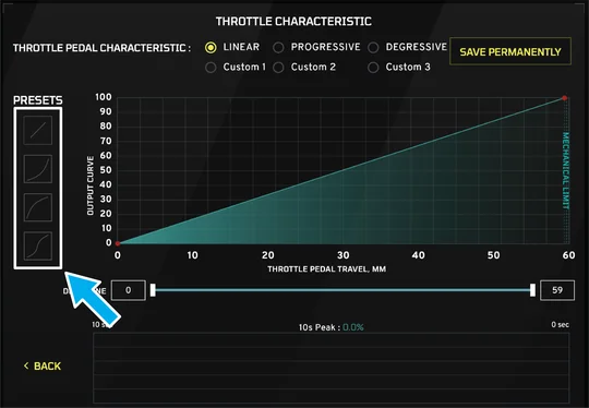
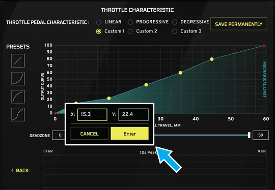
OUTPUT CURVE (CUSTOM)
Select a "CUSTOM" profile to adjust each point along the curve. Up to three custom profiles can be stored and selected through the Fanatec Tuning Menu.
| TIP: By clicking on a curvature point, you can set the X and Y values of that specific point to your precise preference. |
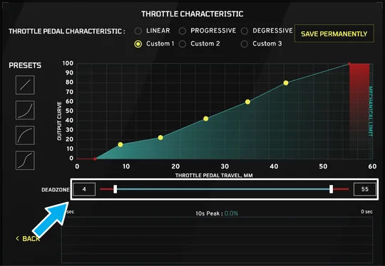
DEADZONE
The start and end of the pedal travel can be set by selecting a deadzone according to your preference.
BRAKE
| NOTE: Do not forget to click on "SAVE PERMANENTLY" to save your settings once complete. |
BRAKE FORCE
Set the Brake Force "BRF" by moving the slider on the right side of the brake input window.
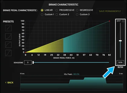

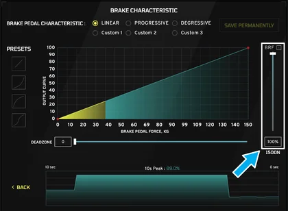
OUTPUT CURVE (PRESETS)
Select either "LINEAR", "PROGRESSIVE", or "DEGRESSIVE" for the simplest curve adjustment according to your preference.
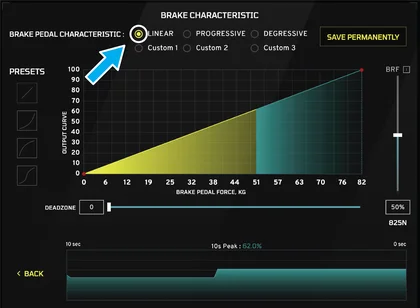
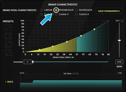
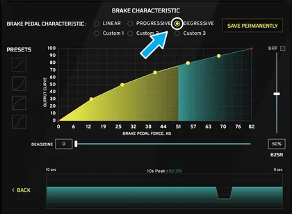
For more advanced curve adjustments, select a "PRESET" according to your preference.
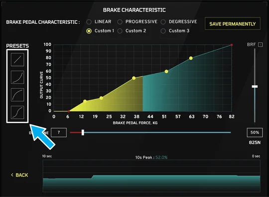
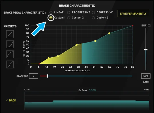
OUTPUT CURVE (CUSTOM)
Select a "CUSTOM" profile to adjust each point along the curve. Up to three custom profiles can be stored and selected through the Fanatec Tuning Menu.
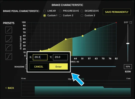
| TIP: By clicking on a curvature point, you can set the X and Y values of that specific point to your precise preference. |
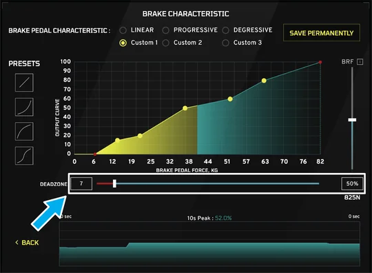
DEADZONE
The start of the pedal travel can be set by selecting a deadzone according to your preference.
H - MAINTENANCE
Use a dry, lint-free cloth to wipe off excess dust.
| CAUTION: Do not use any cleaning solutions or water! |
Do not overtighten the bolts when hard-mounting.
| NOTE: If lubrication of the pivot points is required after prolonged use, apply lithium grease only. |
I - WARRANTY
The product warranty is provided by CORSAIR MEMORY, Inc. Refer to the terms & conditions of CORSAIR MEMORY, Inc. on Fanatec.com.
J - LEGAL
©2026 CORSAIR MEMORY, Inc. Trademarks belong to their respective owners. All rights reserved. Fanatec is a brand of CORSAIR MEMORY Inc.