MANUEL | GUIDE DE DÉMARRAGE RAPIDE
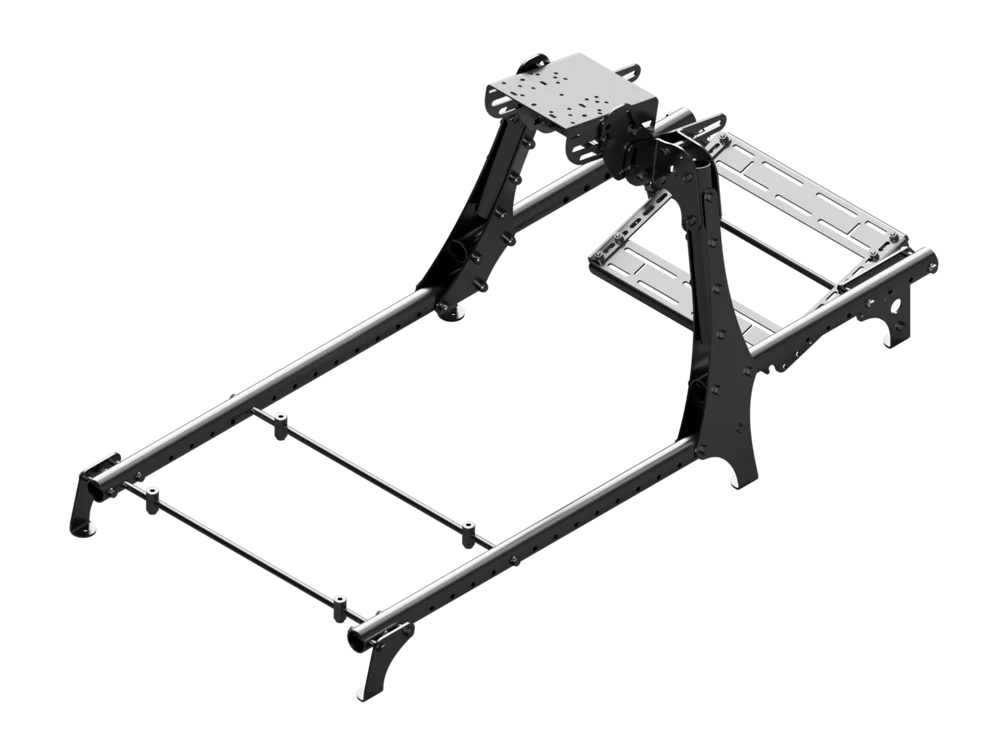
Cockpit CSL
La version anglaise est disponible ici - English
Si vous rencontrez d'autres problèmes, veuillez contacter support client
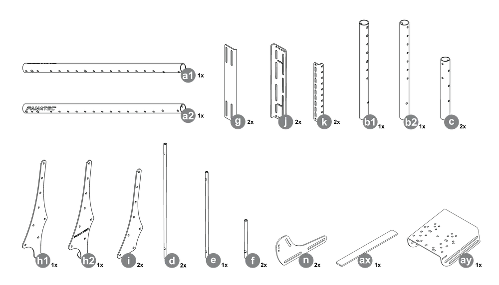
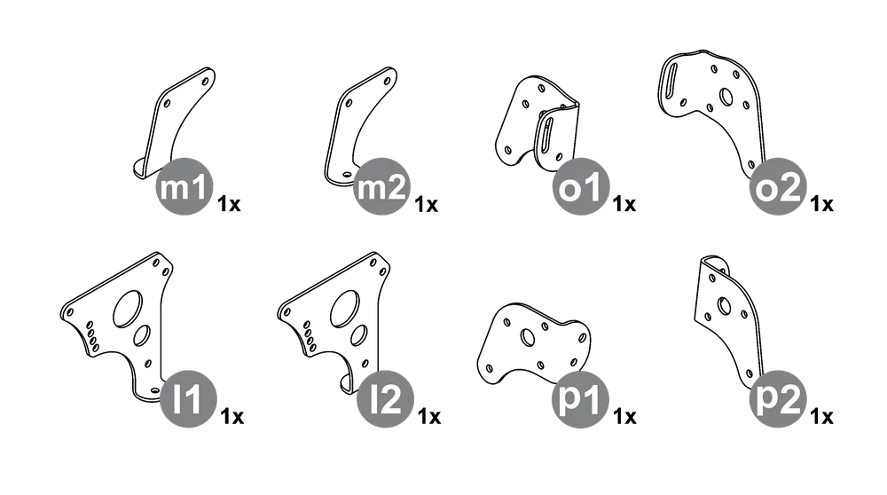
CONTENU DE L'EMBALLAGE
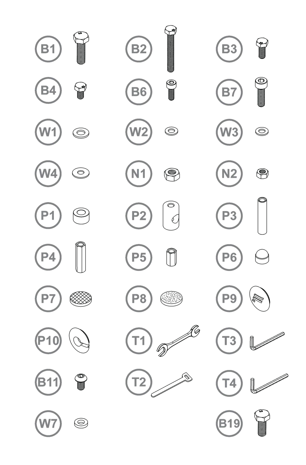
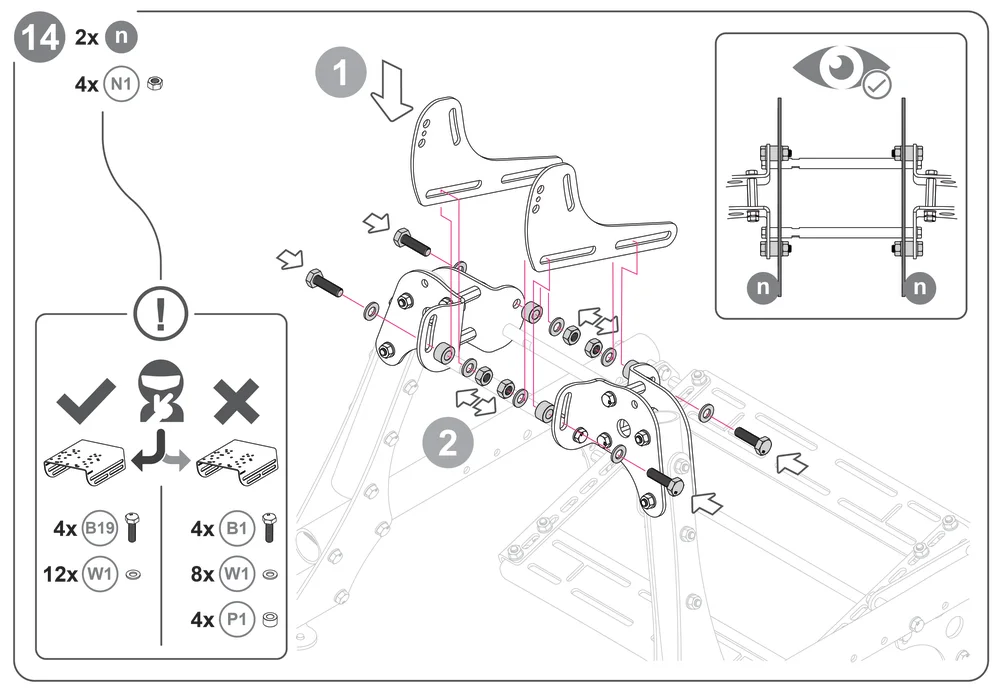
B1 - 4x - M10 x 35 mm
B2 - 20x - M8 x 60 mm
B3 - 8x - M8 x 20 mm
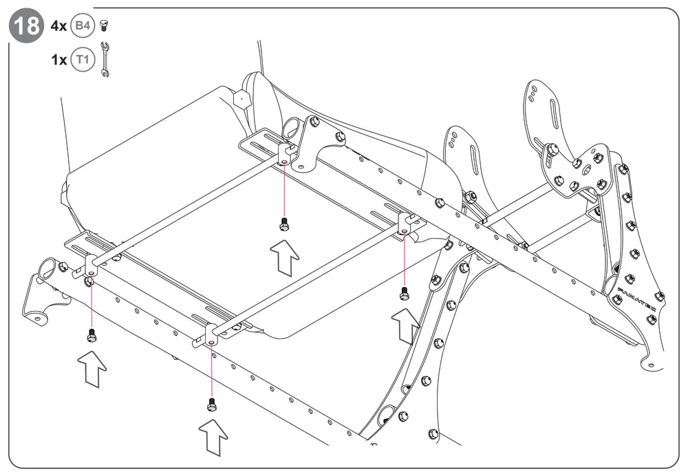
B4 - 46x - M8 x 14 mm
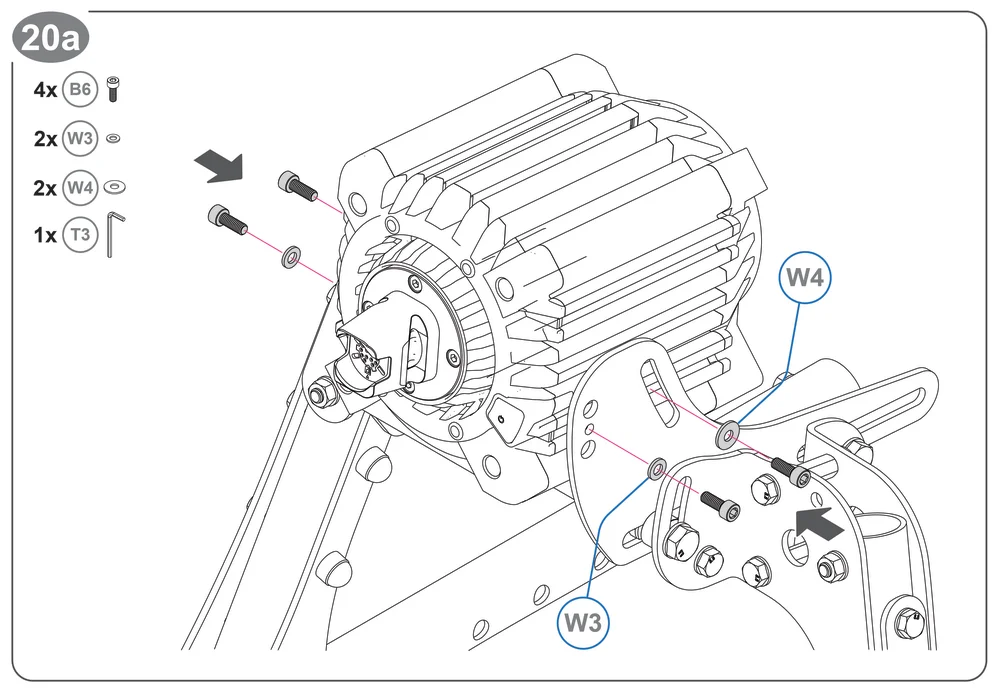
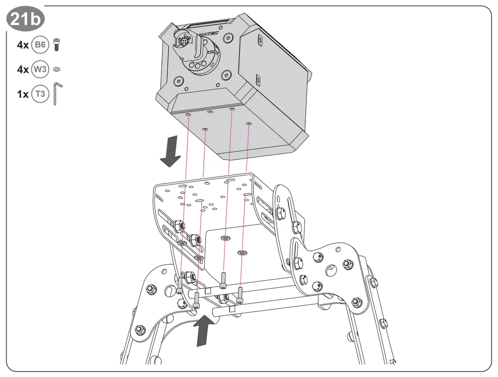
B6 - 4x - M6 x 16 mm
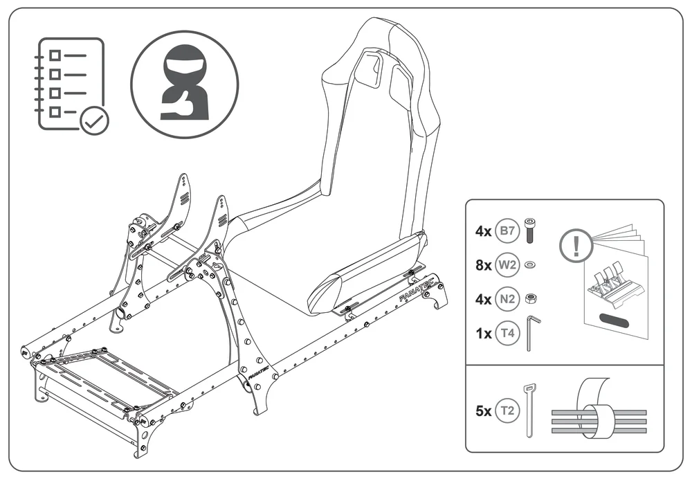
B7 - 4x - M8 x 25 mm
W1 - 24x - Rondelle M10
W2 - 110x - Rondelle M8
W3 - 4x - Rondelle M6
W4 - 4x - Rondelle M8
N1 - 4x - Écrou M10
N2 - 32x - Écrou M8
P1 - 4x - Entretoise M10
P2 - Écrou cylindrique M8
P3 - Tige M8
P4 - 4x - Écrou hexagonal M8 (long)
P5 - 4x - Écrou hexagonal M8 (court)
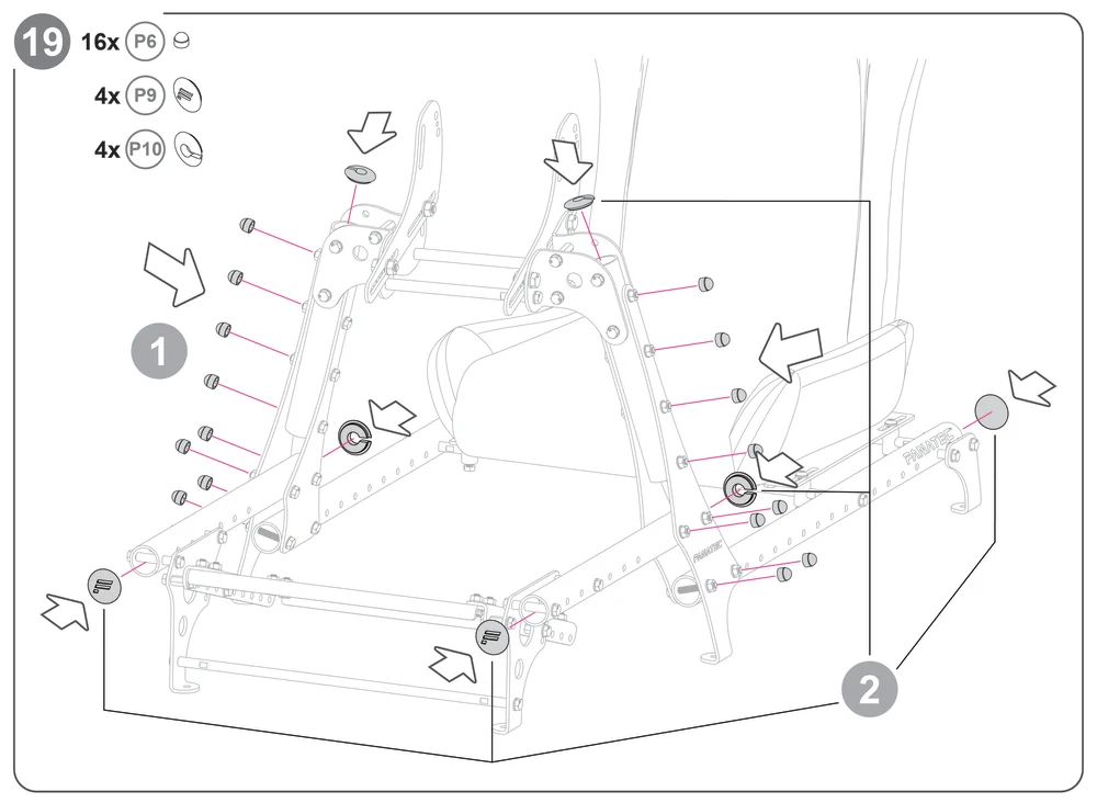
P6 - 16x - Bouchons de 13 mm
P7 - 6x - Patins en caoutchouc
P8 - 6x - Patins en feutre
P9 - 4x - Bouchons de tube
P10 - 4x - Embouts de câble
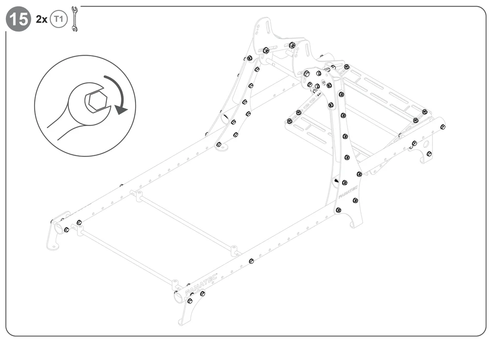
T1 - 2x - 13 mm / 16 mm
T3 - 1x - 5 mm
B11 - 4x - M8 x 14 mm
T2 - 5x - Bande Velcro
T4 - 1x - 6 mm
W7 - 4x - M8 Rondelle de 3 mm
B19 - 8x - M10 x 25 mm
REMARQUE : Siège vendu séparément !

B12 - 4x - M8 x 20 mm
POUR COMMENCER


Facultatif
ENSEMBLE COCKPIT


REMARQUE : avant de continuer, consultez le manuel du support de moniteur CSL Cockpit si vous assemblez le cockpit avec le support de moniteur.


Poursuivez avec les étapes 20a, 20b ou 20c, selon votre empattement.
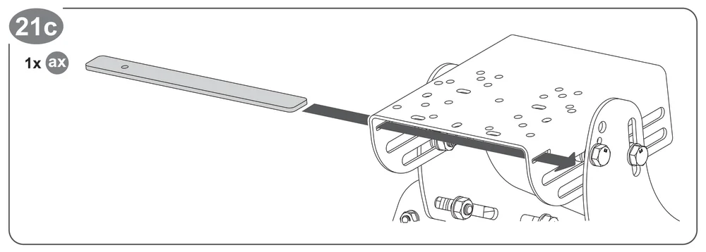
REMARQUE : les étapes 20c à 23c s'adressent spécifiquement aux propriétaires de modèles G29 / 920 / 923.
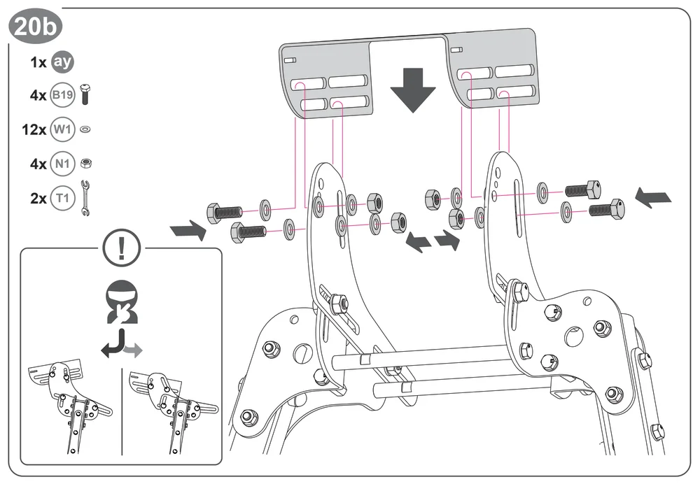
REMARQUE : Positionnez la pièce «ay » à l'angle souhaité.
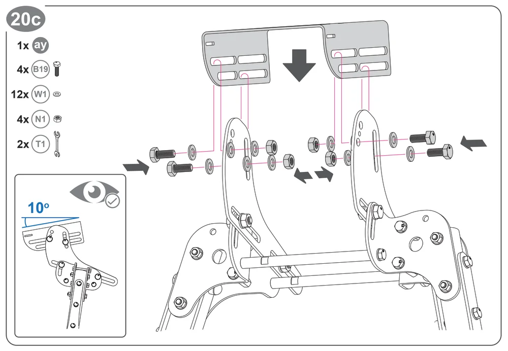
REMARQUE : le positionnement de la pièce «ay » à un angle de 10 degrés vers le bas est optimal pour les modèles G29 / 920 / 923.
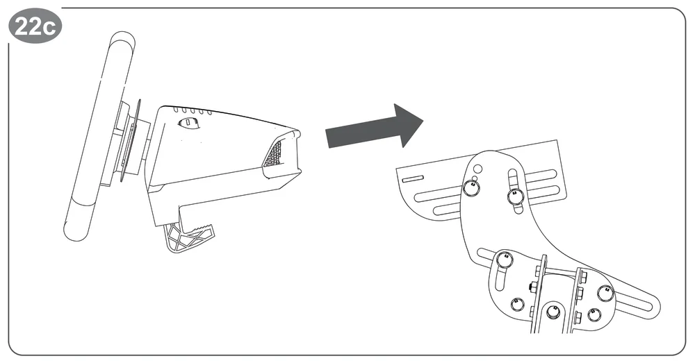
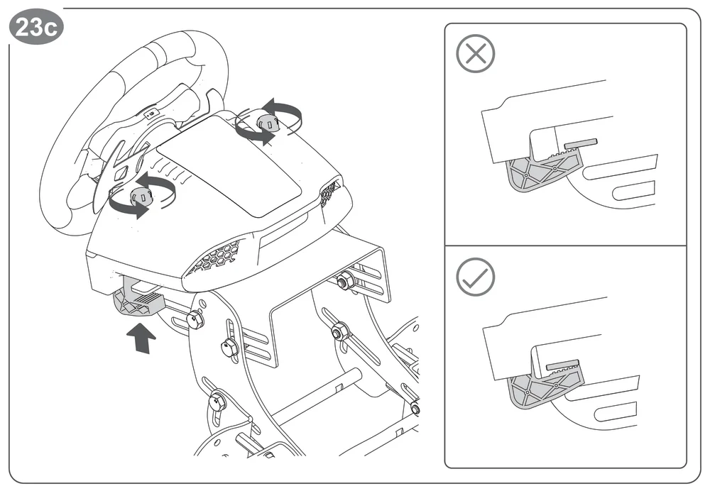
Aucun boulon supplémentaire n'est nécessaire pour fixer davantage les modèles G29 / 920 / 923.
Fanatec.com/manuels
ASSISTANCE
La garantie du produit est fournie par Corsair Memory, Inc. Reportez-vous à la fiche de garantie fournie ainsi qu'aux conditions générales de Corsair Memory, Inc. sur www.fanatec.com.