-
BEFORE YOU START
-
WHAT'S INCLUDED - BOX CONTENTS
-
USING THE L-SHAPED HANDLE BOLT LOCKING MECHANISM
-
ASSEMBLING THE COCKPIT FRAME
-
INSTALLING THE PEDAL AND STEERING ASSEMBLIES
-
INSTALLING THE ONBOARD MONITOR MOUNT
-
OPTIONAL: INSTALLING THE TWO-PIECE BUCKET SEAT
-
OPTIONAL: INSTALLING THE SHIFTER MOUNTING KIT
-
OPTIONAL: INSTALLING THE KEYBOARD TRAY ASSEMBLY
-
OPTIONAL: INSTALLING THE FRONT MOUNT BRACKET ASSEMBLY
-
OPTIONAL: INSTALLING THE LEFT AND RIGHT UPPER ACCESSORY MOUNTS
-
OPTIONAL: INSTALLING THE ACCESSORY PC TRAY
-
OPTIONAL: INSTALLING THE INVERTED PEDAL BRACKETS
-
OPTIONAL: INSTALLING THIRD-PARTY ACCESSORIES
-
SETUP AND ADJUSTMENT SUGGESTIONS
-
CARE AND MAINTENANCE
-
WARRANTY
-
LEGAL
MANUAL | QUICK START GUIDE
ClubSport GT Cockpit (Black)
RACING SIMULATOR COCKPIT

BEFORE YOU START
Congratulations on purchasing your new Fanatec ClubSport GT cockpit.
Please take a moment to carefully read this guide prior to assembling.
|
CAUTION: Your cockpit is engineered from steel for strength and durability.
|
WHAT'S INCLUDED - BOX CONTENTS
BOX 1 CONTENTS

Left Side Front Frame Assembly

Right Side Front Frame Assembly

Left Side Rear Frame Assembly

Right Side Rear Frame Assembly

Connecting Brackets
(Left and Right are identical)

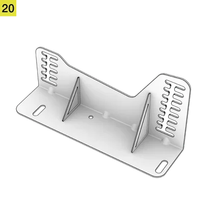
Rear Connecting Plate

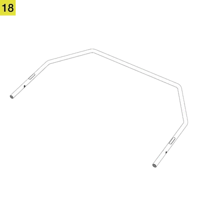
Lower Front Connecting Tube
(Long)

Upper Front Connecting Tube
(Short)

Front Panel

Top Panel

BOX 1 INCLUDED HARDWARE

Tool Kit Bag:
M5 Allen Key (1x)
• M6 Allen Key (1x)
• M8 Allen Key (1x)
• M8 Open-ended Wrench (1x)
• M12 Open-ended Wrench (1x)

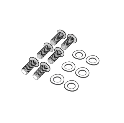
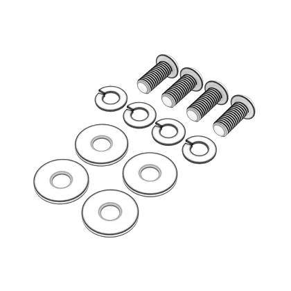
Spare Parts Bag:
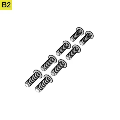
M5 16mm Bolts (2x)
• M5 Spring Washers (2x)
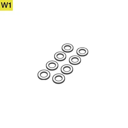
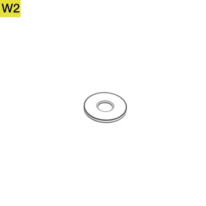
• M5 Washers (2x)
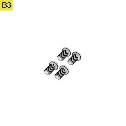
• M6 12mm Bolts (2x)
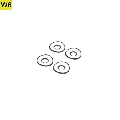
• M6 Curved Washers (2x)
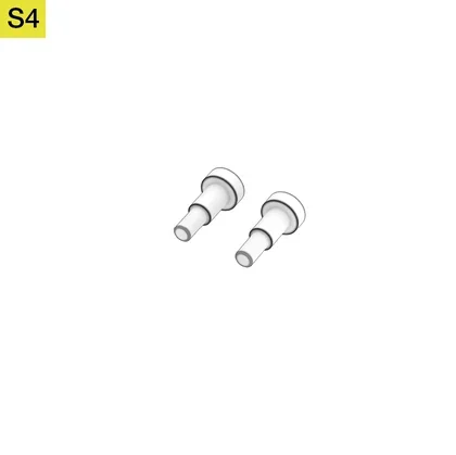
• M6 Shoulder Bolt (1x)
• M8 16mm Bolts (2x)
• M8 20mm Bolts (2x)
• M8 35mm Bolts (2x)
• M8 Curved Washers (2x)
• M8 Washers (2x)
• R-pin (1x)

Sticker & Velcro Bag:
Four-color Arrow Labels (4x)
• Velcro, Black (4x)

Sticker & Velcro Bag:
• Four-color Arrow Labels (4x)
• Velcro, White (4x)
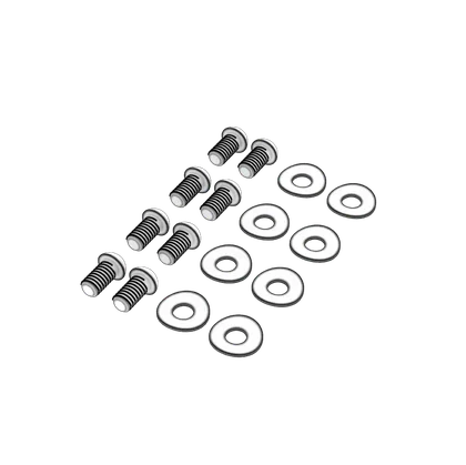
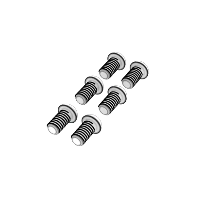
Step 1 Bag:
• M8 20mm Bolts (6x)
• M8 Curved Washers (6x)
Step 2 Bag:
• M8 20mm Bolts (6x)
• M8 Curved Washers (6x)

Step 3A Bag:
• M8 35mm Bolts (2x)
Step 3B Bag:
• M8 35mm Bolts (2x)
Step 4 Bag:
• M6 12mm Bolts (8x)
• M6 Curved Washers (8x)
Step 5 Bag:
• M6 12mm Bolts (8x)
• M6 15mm L-Bolts (8x)
Step 6 Bag:
• M12 Rubber Feet (4x)
BOX 2 CONTENTS

Pedal Mounting Assembly (pre-assembled)
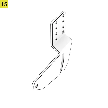
Onboard Monitor Mount Upright

Onboard Monitor Mount Base
VESA Mount 100mm x 100mm
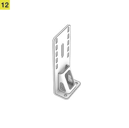
Right Steering Mount Bracket

Left Steering Mount Bracket
Main Wheelbase Mounting Plate
Seat Slider Adjustment Handle

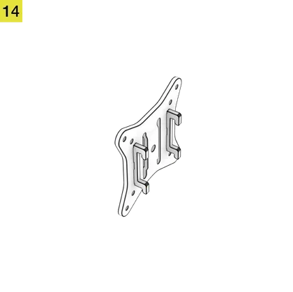
Left Side Seat Mounting Bracket
Right Side Seat Mounting Bracket

BOX 2 INCLUDED HARDWARE

Step 8C Bag:
• M6 15mm L-Bolts (2x)
Step 9 Bag:
• M6 12mm Bolts (6x)
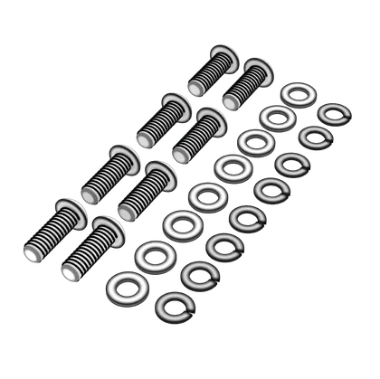
Step 10A Bag:
• M5 16mm Bolts (8x)
• M5 Spring Washers (8x)
• M5 Washers (8x)
Step 10B Bag:
• M6 Shoulder Bolts (2x)
• M8 20mm L-Bolts (2x)
• M8 Spring Washers (2x)
• M8 Washers (4x)
• Locking Pin (1x)
Step 11A Bag:
• M8 16mm Bolts (4x)
Step 11B Bag:
• M8 20mm Bolts (2x)
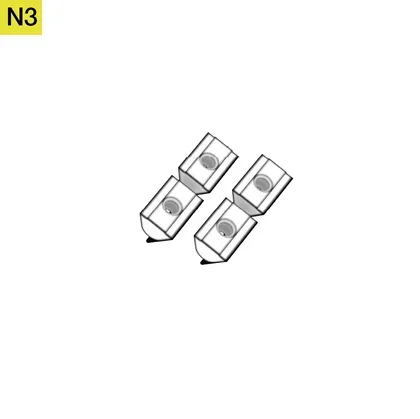
• M8 Nuts (2x)
• M8 T-Bolt (1x)
• M8 Washer (1x)
Step 11C Bag:
• M4 12mm Screws (4x)
• M4 15mm Spacer Screws (4x)
• M4 30mm Spacer Screws (4x)
• M4 40mm Spacer Screws (4x)
• M4 Allen Key (1x)

Seat Assembly Bag:
• M8 15mm Bolts (4x)
• M8 20mm Bolts (4x)
• M8 Allen Key (1x)

Seat Step 1A Bag:
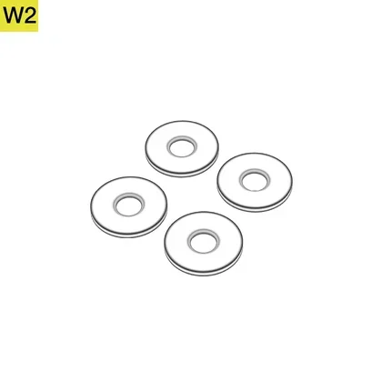
• M8 40mm Plastic Washers (4x)
• M8 25mm L-Bolts (4x)
• M8 Washers (4x)

Seat Step 1B Bag:
• R-pins (2x)
Seat Step 1C Bag:
• M8 20mm Bolts (4x)
• M8 Spring Washers (4x)
• M8 Washers (4x)
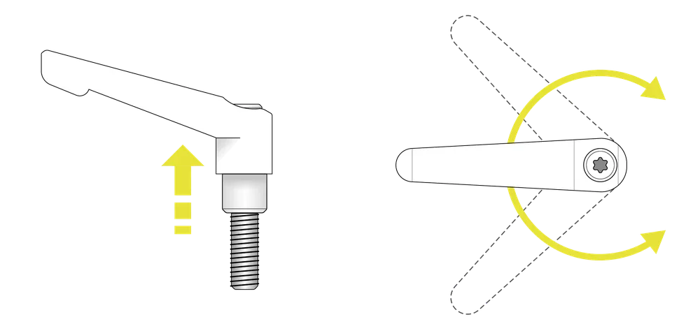
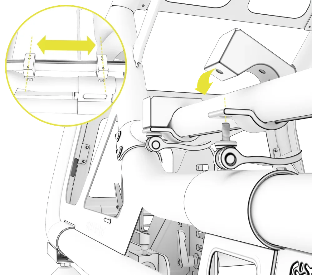
USING THE L-SHAPED HANDLE BOLT LOCKING MECHANISM
DISENGAGING THE LOCKING MECHANISM
Pull the handle outward to disengage the lock, allowing it to rotate freely in either direction.
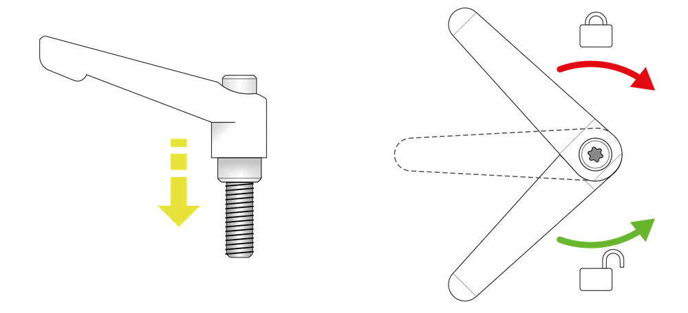
ENGAGING THE LOCKING MECHANISM
Release the handle in the desired position to re-engage the lock. Rotate it counterclockwise to loosen or clockwise to tighten the threaded bolt.
ASSEMBLING THE COCKPIT FRAME
| NOTE: We recommend that you do not fully tighten the bolts until step 5 is completed. |
Begin the assembly of your Fanatec ClubSport GT cockpit frame by unpacking the components from Box 1. Follow the steps for assembly of the cockpit frame laid out in this section.
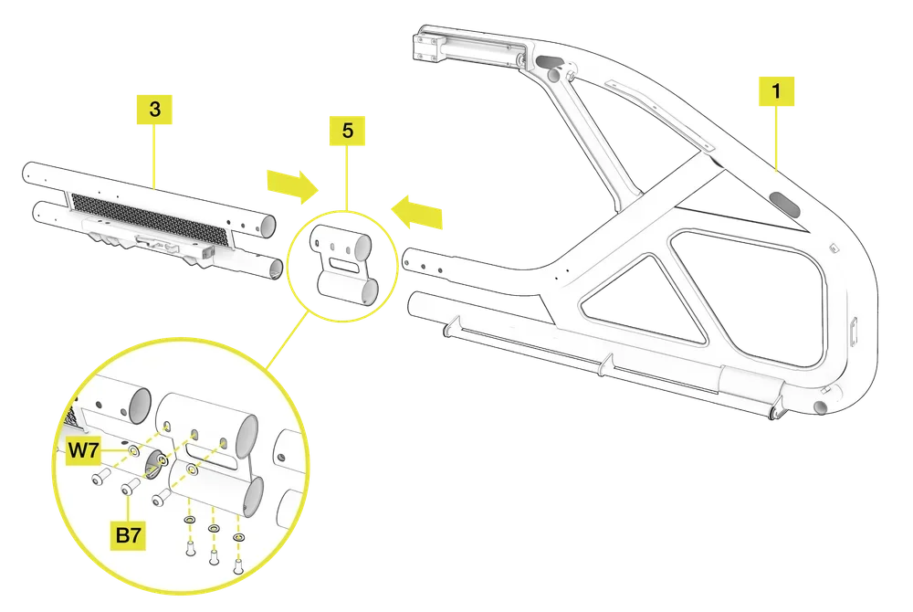
1: ASSEMBLING THE LEFT SIDE OF THE MAIN FRAME
Open the tool and hardware bags labeled STEP 1 and HARDWARE KIT. To complete the step, the following hardware and tools will be used:

M8 Allen Key

M8 20mm Bolts (6x)
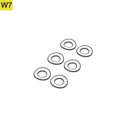
M8 Curved Washers (6x)
- Slide the Left Side Front Frame Assembly (1) and Left Side Rear Frame Assembly (3) into the Connecting Bracket (5).
- Ensure the mounting holes on all three pieces (1, 3, 5) are aligned.
- Screw six M8 20mm Bolts (B7) and Curved Washers (W7) into the mounting holes to connect the sections of the main frame together. The concave side of the curved washer must face the frame.
| TIP: First screw in the three M8 20mm Bolts on the bottom of the connecting bracket (5). |
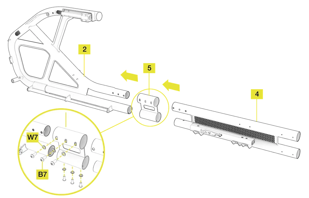
2: ASSEMBLING THE RIGHT SIDE OF THE MAIN FRAME
Open the hardware bag labeled STEP 2.
To complete the step, the following hardware and tools will be used:
M8 Allen Key
M8 20mm Bolts (6x)
M8 Curved Washers (6x)
- Slide the Right Side Front Frame Assembly (2) and Right Side Rear Frame Assembly (4) into the Connecting Bracket (5).
- Ensure the mounting holes on all three pieces (2, 4, 5) are aligned.
- Screw six M8 20mm Bolts (B7) and Curved Washers (W7) into the mounting holes to connect the sections of the main frame together. The concave side of the curved washer must face the frame.
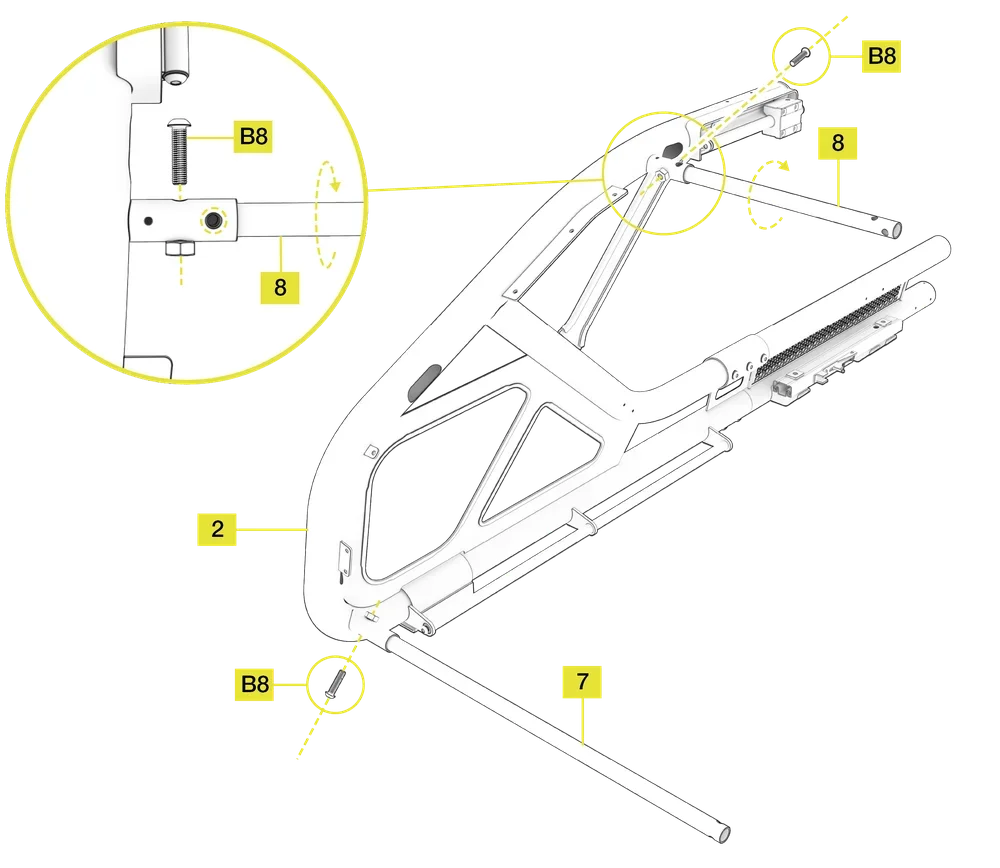
3A: INSERTING UPPER AND LOWER CONNECTING TUBES
Open the hardware bag labeled STEP 3A.
To complete the step, the following hardware and tools will be used:
M8 Allen Key

M8 35mm Bolts (2x)
- Insert the Lower Connecting Tube (7) into the bottom tubular bracket located near the base of the Right Side Front Frame Assembly (2). Secure the Lower Connecting Tube (7) by partially screwing in one M8 35mm Bolt (B8).
- Insert the Upper Connecting Tube (8) into the top tubular bracket located near the top of the Right Side Front Frame Assembly (2).
- Rotate the Upper Connecting Tube (8) so that all holes align with the holes in both tubular mounting brackets of the frame.
- Secure the Upper Connecting Tube (8) by screwing in one M8 35mm Bolt (B8).
3B: ADDING THE LEFT SIDE OF THE FRAME
Open the hardware bag labeled STEP 3B.
To complete the step, the following hardware and tools will be used:
M8 Allen Key
M8 35mm Bolts (2x)
- Carefully align the left side of the assembled frame (1 and 3) with the Upper Connecting Tube (8) and the Lower Connecting Tube (7). Insert tubes into their respective tubular brackets of the left side of the assembled frame (2 and 4).
- Secure the Upper Connecting Tube (8) by screwing in one M8 35mm Bolt (B8).
- Secure the Lower Connecting Tube (7) by partially screwing in one M8 35mm Bolt (B8).

4: ATTACHING THE CONNECTING PANEL
Open the hardware bag labeled STEP 4.
To complete the step, the following hardware and tools will be used:

M6 Allen Key
M6 12mm Bolts (8x)

M6 Curved Washers (8x)
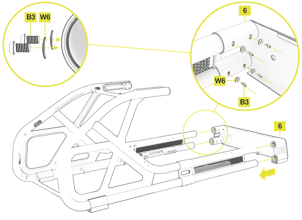
- Slide the Rear Connecting Plate (6) over the left and right rear frame tubular sections and align the corresponding holes in the Connecting Plate (6) with the pre-drilled frame holes.
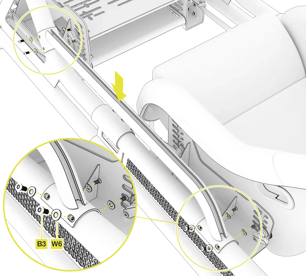
- Secure the left and right rear frame tubular sections to the Connecting Plate (6) by screwing in eight M6 12mm Bolts (B3) and Curved Washers (W6). The concave side of the curved washer must face the frame.
5: ATTACHING THE TOP PANEL
Open the hardware bag labeled STEP 5.
To complete the step, the following hardware and tools will be used:
M6 Allen Key
M6 12mm Bolts (8x)

M6 15mm L-Bolts (2x)
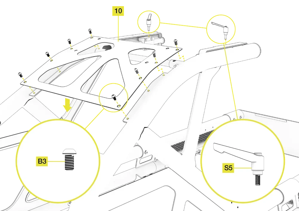
- Place the Top Panel (10) on the top of the main frame and align the corresponding holes in the panel with the pre-drilled frame tabs.
- Secure the Top Panel (10) to the main frame tabs by screwing in eight M6 12mm Bolts (B3).
- Screw two M6 15mm L-Bolts (S5) into the aluminium radial sliding blocks on the left and right side of the steering mount.
| NOTE: We recommend tightening all bolts at this step except for the two Bottom Connecting Tube (7) M8 35mm bolts (B8) from steps 3A and 3B. |
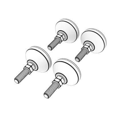
6: ATTACHING THE RUBBER FEET
Open the hardware bag labeled STEP 6.
To complete the step, the following hardware and tools will be used:
M12 Open-Ended Wrench

M12 Rubber Feet (4x)
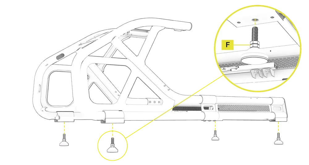
- Roll the cockpit frame onto its side to allow access to the foot brackets.
- Attach the Rubber Feet (F) to each foot bracket on the underside of the assembled frame and screw them all the way in until the locking nut makes contact.
| NOTE: If you encounter resistance when attaching the feet to the frame, use an M12 Open-ended Wrench to gently tighten them. Avoid using excessive force to prevent stripping the threads. |
INSTALLING THE PEDAL AND STEERING ASSEMBLIES
Continue with the assembly of your Fanatec ClubSport GT cockpit by unpacking the components from Box 2.
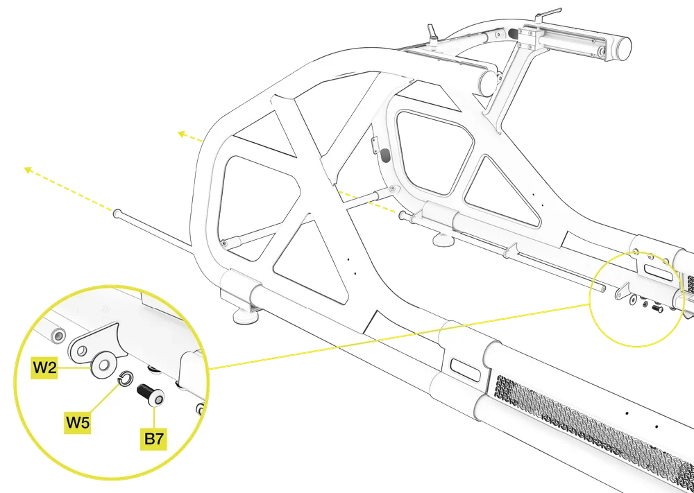
7: PREPARING THE FRAME AND THE PEDAL MOUNTING ASSEMBLY
To complete the step, the following tool will be used:
M8 Allen Key
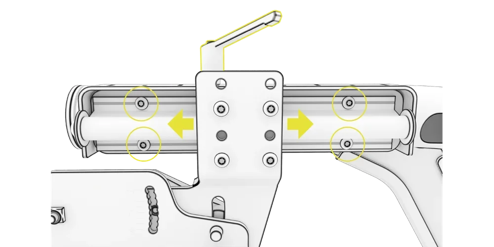
- Remove the rear two M8 20mm Bolts (B7), two M8 Spring Washers (W5), and two M8 Washers (W2) that secure the sliding rods as indicated in the image.
- Slide the steel rods out of their brackets via the front of the cockpit. See the direction of the arrows in the image below.
| NOTE: The M8 bolts and washers positioned on the front of the sliding rods do not have to be removed in order to complete this step. |
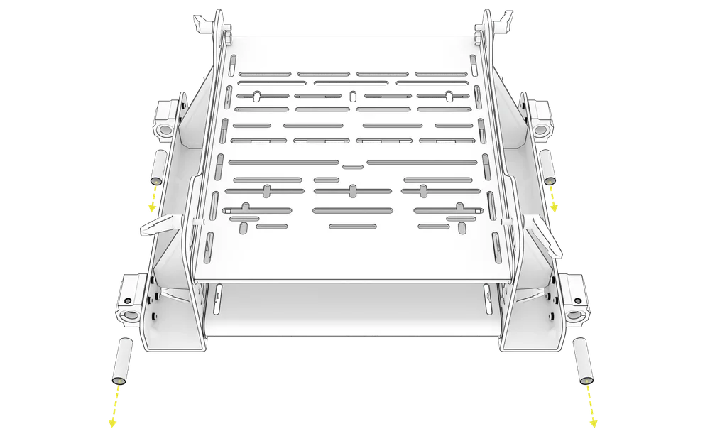
3. Remove the protective PVC plugs from all four aluminium sliding radial blocks of the Pedal Mounting Assembly (11) prior to the installation.
| NOTE: The Pedal Mounting Assembly (11) with eight M8 20mm L-Bolts and corresponding M8 washers is pre-assembled at the factory. |
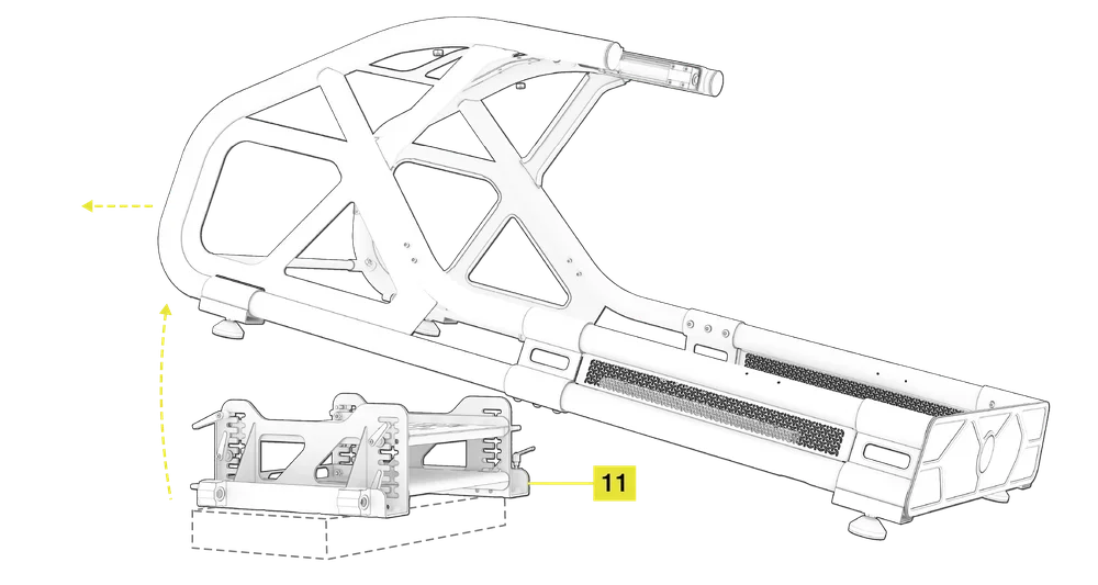
8A: PLACING THE PEDAL MOUNTING ASSEMBLY
| CAUTION: The Pedal Mounting Assembly is heavy. Please exercise caution when handling. Two people are recommended for lifting. |
| NOTE: For ease of the installation, lay the Front and Top panel packing box in front of the Pedal Mounting Assembly. Place the Pedal Mounting Assembly (11) on the packaging box in front of the cockpit frame with the powerbrick holder oriented towards the front of the cockpit. |
- Carefully lift the front of the frame high enough to clear the Pedal Mounting Assembly (11).
- Position the cockpit frame over the Pedal Mounting Assembly (11).
- Align the pre-attached aluminium sliding radial blocks on the pedal side brackets with the steel rods at the same height as the bracket.
8B: SECURING THE PEDAL MOUNTING ASSEMBLY

M5 Allen Key
M8 Allen Key
- Reinsert the steel sliding rods removed in step 7, making sure they pass through the aluminium blocks on the sides of the Pedal Mounting Assembly (11).
- Push the rods all the way in and secure them with two previously removed M8 20mm Bolts (B7), two Spring Washers (W5) and two M8 Washers (W2).
| IMPORTANT: Ensure aluminium radial blocks of the Pedal Assembly (11) are aligned with the steel rod brackets on the main frame. If there is any resistance when sliding the rods through the blocks, do not force them through. Check for alignemt or any blockage and complete the step with due care. |

| NOTE: Check the smoothness of the sliding rods and radial bearing blocks by gently sliding the Pedal Mounting Assembly back and forth. |
IF THE PEDAL MOUNTING ASSEMBLY DOESN'T SLIDE SMOOTHLY ...
- Loosen the L-shaped bolts clamping the radial bearing blocks to the steel sliding rods.
- Slightly loosen the eight bolts holding the radial bearing blocks on the Pedal Mounting Assembly (11) on each side, move the assembly to the center of the rail and re-tighten all the bolts.

8C: ADDING THE L-BOLTS TO THE PEDAL MOUNTING ASSEMBLY
To complete the step, the following hardware and tools will be used:
M6 Allen Key
M8 Allen Key

M6 15mm L-Bolts (2x)
| CAUTION: The L-Bolts must be securely tightened prior to any use of the cockpit to prevent the pedal assembly from sliding forward when applying pressure to the pedals. |
- Once the Pedal Mounting Assembly (11) is installed on the steel sliding rods, add two M6 15mm L-Bolts (S5) to the aluminium sliding radial blocks and tighten them securely.

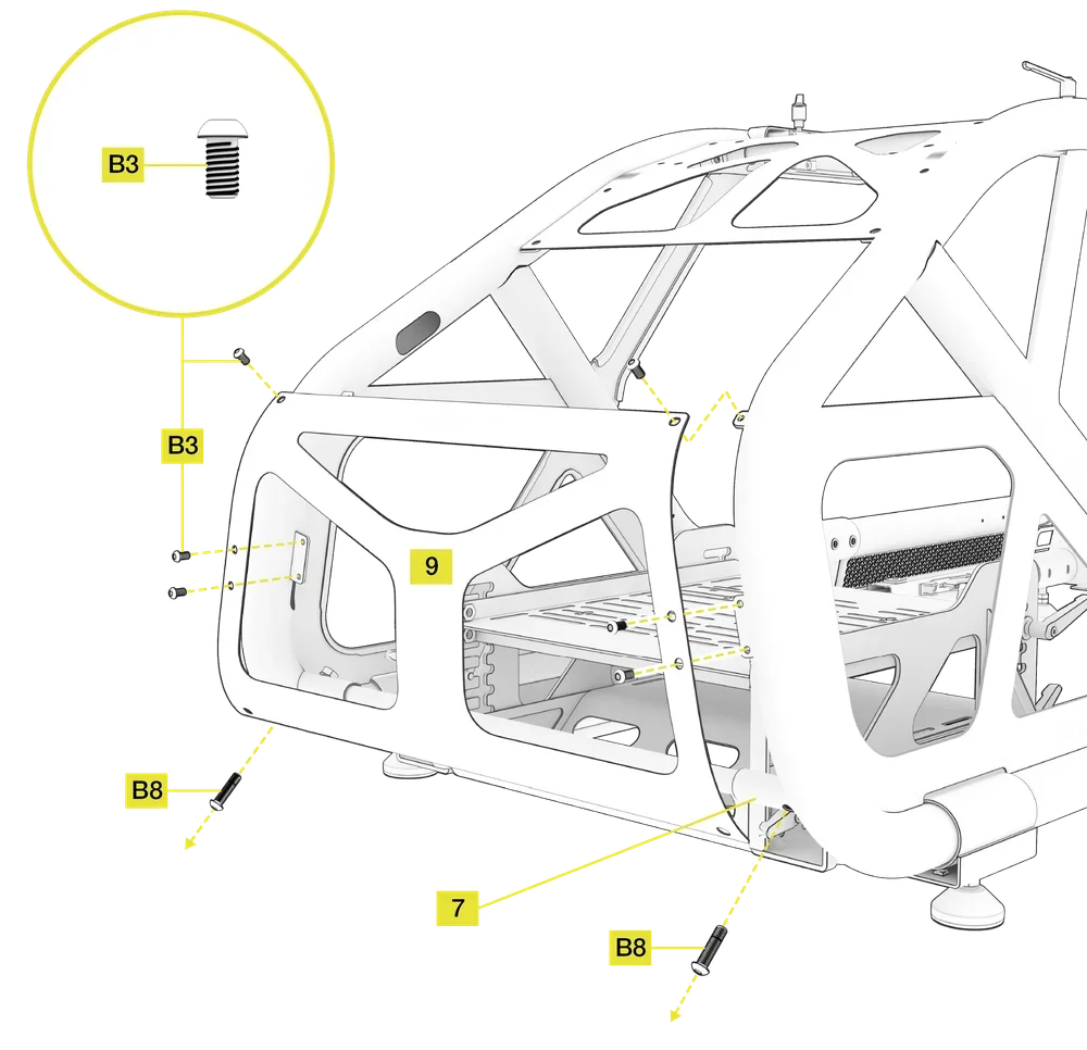
9: ATTACHING THE FRONT PANEL
Open the hardware bag labeled STEP 9.
To complete the step, the following hardware and tools will be used:
M6 Allen Key
M8 Allen Key
M6 12mm Bolts (6x)
- Remove the two M8 35mm Bolts (B8) from the Lower Connecting Tube (7).
- Place the Front Panel (9) on the front of the main frame so that its holes align with the corresponding holes of the frame.
- Screw in six M6 12mm Bolts (B3) to secure the Front Panel (9) to the main frame tabs.
- Screw the two M8 35mm Bolts (B8) back into the Lower Connecting Tube (7) so that they pass through the Front Panel (9).
10A: ASSEMBLING THE STEERING MOUNT
Open the hardware bag labeled STEP 10A.
To complete the step, the following hardware and tools will be used:
M5 Allen Key
M5 16mm Bolts (8x)

M5 Spring Washers (8x)
M5 Washers (8x)
- Determine the wheelbase height and choose the preferred set of four mounting holes. Use the lowest positioned four holes for smaller wheelbases and highest positioned four holes for taller wheelbases.
- Using eight M5 16mm Bolts (B2), eight M5 Washers (W1) and eight M5 Spring Washers (W4), secure the Right Steering Mount Bracket (15) and the Left Steering Mount Bracket (16) to the pre-installed aluminum sliding radial blocks on the right and left frame sections.

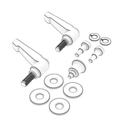
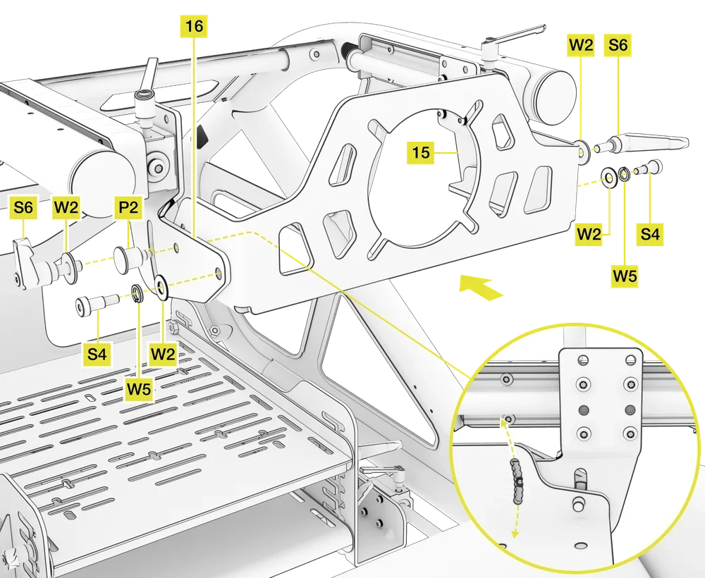
10B: ASSEMBLING THE DIRECT DRIVE UNDER MOUNT
Open the hardware bag labeled STEP 10B.
To complete the step, the following hardware and tools will be used:
M8 Allen Key
M6 Allen Key

M8 20mm L-Bolts (2x)
M6 Shoulder Bolts (2x)
M8 Washers (4x)
M8 Spring Washers (2x)
Locking Pin (1x)
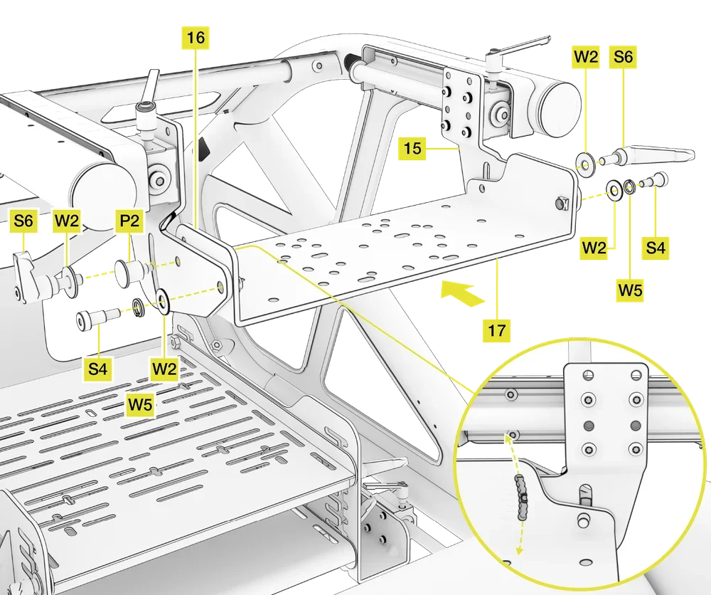
- Attach the Main Wheelbase Mounting Plate (17) to the Right and Left Steering Mount Brackets (15, 16) by using one M6 Shoulder Bolt (S4), one M8 Washer (W2) and one M8 Spring Washer (W5) on each side. Do not overtighten the shoulder bolts.
- Screw in the spring loaded Locking Pin (P2) through the Left Steering Mount Bracket (16) and the left side of the Wheelbase Mounting Plate (17).
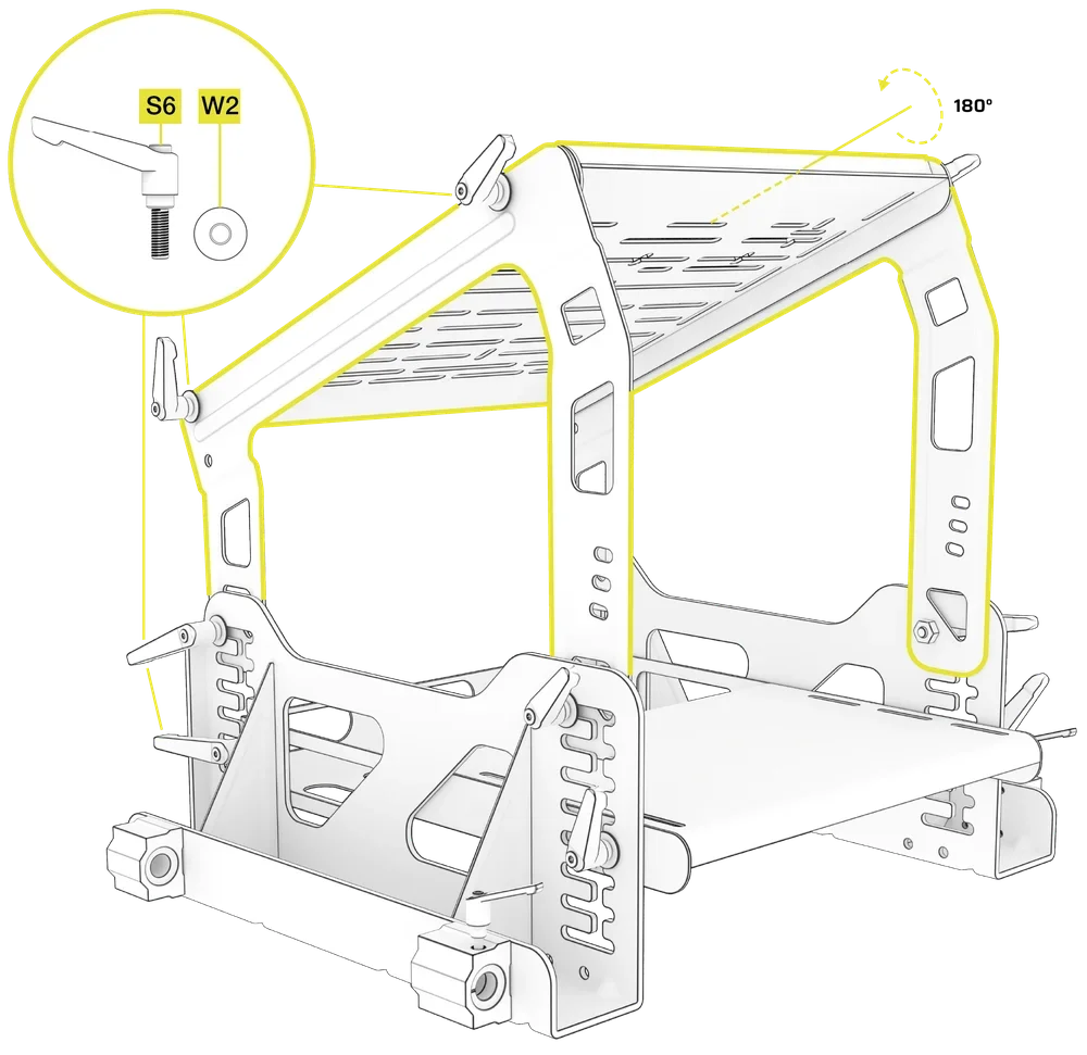
- Screw the two M8 20mm L-Bolts (S6) and two M8 Washers (W2) through the Steering Mount Brackets (15, 16) and into the Wheelbase Mounting Plate (17) on each side.
- To adjust the wheelbase tilt, loosen both L-Bolts (S6), release the Locking Pin (P2) by pulling it outwards, and rotate the plate upwards or downwards. Make sure you retighten the L-Bolts (S6) once you have adjusted the tilt.
|
NOTE: Check the smoothness of the sliding rods and radial blocks by gently sliding the tray assembly back and forth. If the assembly does not slide freely, do the following:
|
INSTALLING THE ONBOARD MONITOR MOUNT
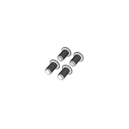
11A: ATTACHING THE ONBOARD MONITOR MOUNT BASE
Open the hardware bag labeled STEP 11A.
To complete the step, the following hardware and tools will be used:
M8 Allen Key
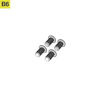
M8 16mm Bolts (4x)
- Attach the Onboard Monitor Mount Base (13) to the top of the main frame using four M8 16mm Bolts (B6).
| NOTE: These four bolts do not require a nut to secure them to the top plate. All holes are pre-threaded. |

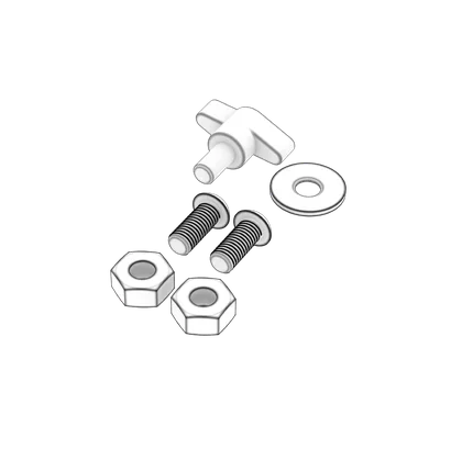
11B: ATTACHING THE ONBOARD MONITOR MOUNT
Open the hardware bag labeled STEP 11B.
To complete the step, the following hardware and tools will be used:
M8 Allen Key

M8 Open-ended Wrench

M8 20mm Bolts (2x)
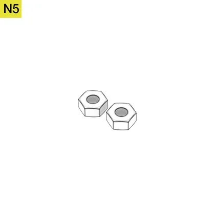
M8 Nuts (2x)
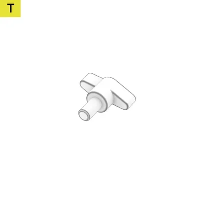
M8 T-Bolt (1x)
M8 Washer (1x)
- Attach the Onboard Monitor Mount Upright (12) to the Onboard Monitor Mount Base (13) using two M8 20mm Bolts (B7) and two M8 Nuts (N5).

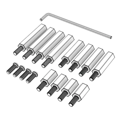
11C: INSTALLING THE ONBOARD MONITOR
Open the hardware bag labeled STEP 11C.
To complete the step, the following hardware and tools will be used:

M4 Allen Key
M4 12mm Bolts (4x)

M4 15mm Spacer Screws (4x)

M4 30mm Spacer Screws (4x)

M4 40mm Spacer Screws (4x)
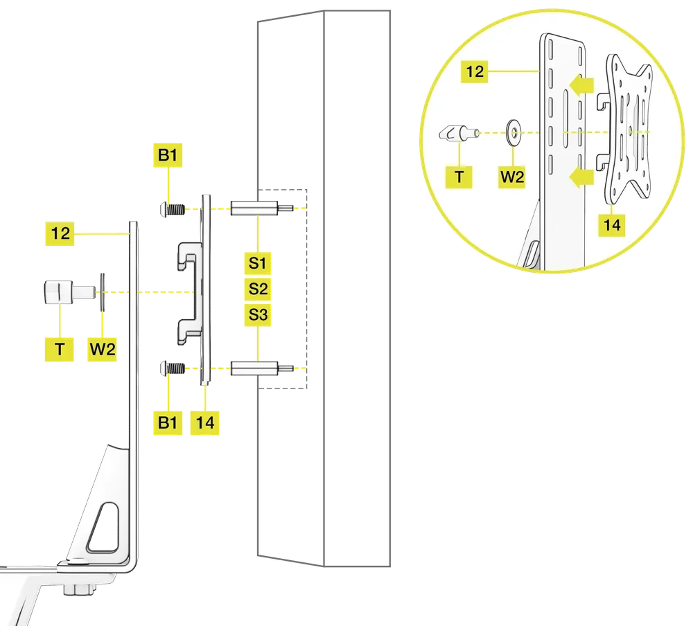
- For recessed VESA mounts, use the appropriate included spacer screws (S1, S2, S3) and screw them into your monitor first.
- Place the VESA Mount (14) over the rear of the monitor or Spacer Screws (S1, S2, S3) and secure it with four M4 12mm Screws (B1).
- Attach the monitor by hooking the VESA Mount (14) into the pre-machined vertical slots in the Onboard Monitor Mount Upright (12).
- Secure the VESA Mount (14) with a T-Bolt (T) and one M8 washer (W2).
| NOTE: All four VESA Mount (14) hooks must engage with the slots in the Onboard Monitor Mount Upright (12). |
OPTIONAL: INSTALLING THE TWO-PIECE BUCKET SEAT
ASSEMBLING THE OPTIONAL TWO-PIECE BUCKET SEAT
Open the hardware bag labeled SEAT ASSEMBLY.
To complete the step, the following hardware and tools will be used:
M8 Allen Key
M8 20mm Bolts (4x)
M8 16mm Bolts (4x)
- Place the seat on a soft floor covering or blanket, laying it on its left side with the right side facing up.
- Insert the top half of the seat into the lower half. Ensure the mounting holes in both seat halves are aligned.
- Screw four M8 20mm Bolts (B7) into the left and right sides of the seat as shown in the image below.
- Screw four M8 16mm Bolts (B6) into the rear section of the seat as shown in the image below.
| NOTE: Only securely tighten the eight bolts once they have all been screwed into the seat. |

INSTALLING THE SEAT BRACKETS
Open the hardware bag labeled SEAT STEP 1A.
To complete the step, the following hardware and tools will be used:
M8 25mm L-Bolts (4x)
M8 Washers (4x)
M8 40mm Plastic Washers (4x)
- Place the seat on a soft floor covering or blanket and lay the seat on its left side.
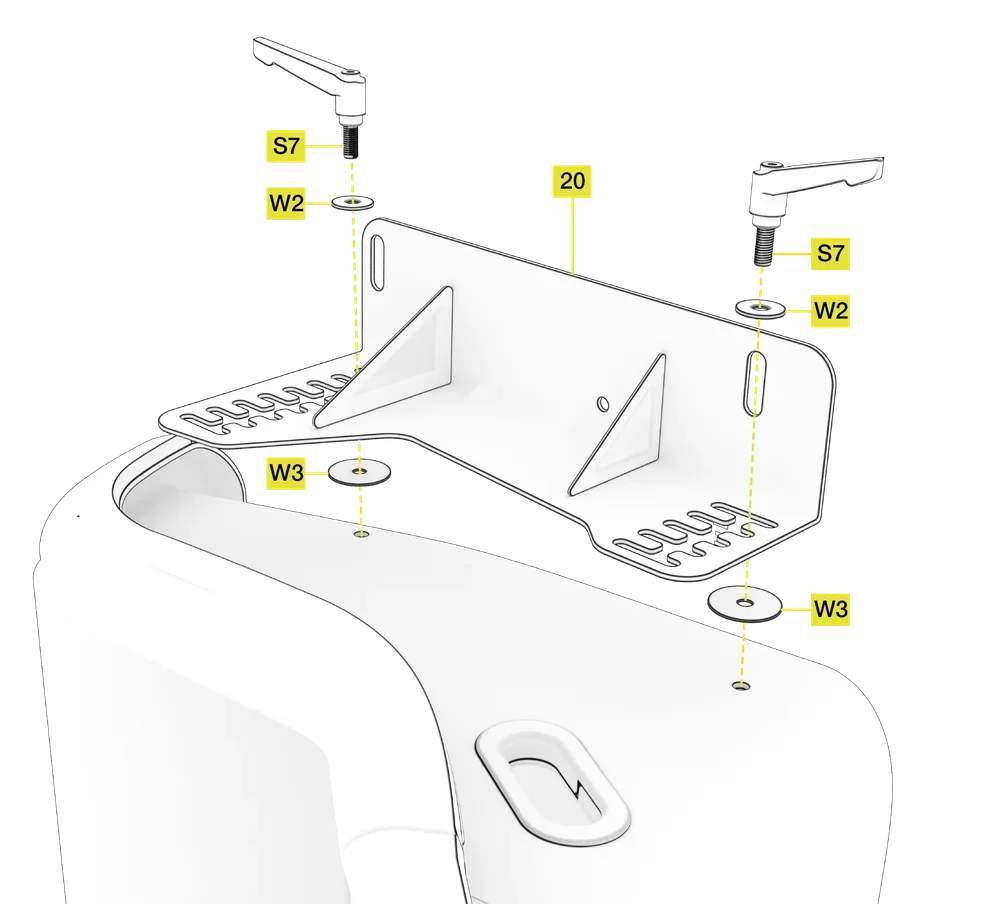
- Place two M8 40mm Plastic Washers (W3) over the pre-drilled threaded holes in the seat side.
- Rest the Right Side Seat Bracket (20) on top of the Plastic Washers (W3) and align the vertical slots of the bracket with the holes in the Plastic Washers (W3) and seat.
- Insert two M8 25mm L-Bolts (S7) with two M8 Washers (W2) into each pre-threaded hole in the seat side. Do not tighten the L-Bolts on the right side of the seat.
- Repeat the process for the opposite side of the seat using the rest of the installation hardware and Left Side Seat Bracket (19).
| NOTE: To adjust the amount of recline and seating position height, undo the L-Bolts and move the seat up or down. Do not tighten the L-Bolts on the right side of the seat yet. See step 1C for when to tighten these L-Bolts. |
INSTALLING THE SEAT SLIDE ASSEMBLY
Open the hardware bag labeled SEAT STEP 1B.
To complete the step, the following hardware will be used:

R-pins (2x)
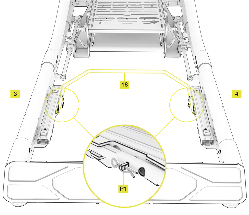
- Ensure that the seat rail sliders on the Left and Right Side Rear Frame Assembly (3, 4) are aligned evenly.
- Position the seat Slider Adjustment Handle (18) between the pre-installed seat rail sliders.
- Secure the handle by inserting the R-pins (P1) through the pre-drilled holes in the left and right seat slider.
| NOTE: Some inwards compression of the seat slider handle is required in order to locate it between the seat slider brackets. |
INSTALLING THE OPTIONAL TWO-PIECE BUCKET SEAT
Open the hardware bag labeled SEAT STEP 1C.
To complete the step, the following hardware and tools will be used:
M8 Allen Key
M8 20mm Bolts (4x)

M8 Spring Washers (4x)
M8 Washers (4x)
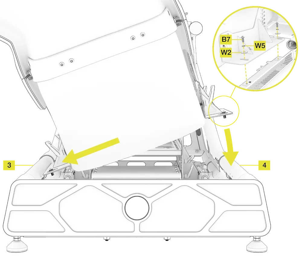
- Insert the seat with attached seat side mounting brackets at an angle into the cockpit as shown in the image below.
- Make sure that the bracket on the opposite side of the seat has enough play to allow it to be angled slightly downward.
- Lower the opposite side of the seat onto the seat slider rail.
- Secure the seat to the sliders by screwing in four M8 20mm Bolts (B7), four M8 Washers (W2) and four M8 Spring Washers (W5).
- Ensure the L-Bolts on both sides of the seat are positioned in the corresponding slots and tighten the L-Bolts on the right side of the seat.
| AFTERMARKET SEATS: Should you wish to mount an aftermarket seat, make sure it has 290mm center-to-center mounting points. There is a limited amount of adjustment for slightly narrower or wider seats. |
OPTIONAL: INSTALLING THE SHIFTER MOUNTING KIT
| IMPORTANT: Do not overtighten any of the cam levers of the clamps in the following chapter. |
| NOTE: The installation process is the same for both left and right versions of the accessories in the following chapter. |
ATTACHING THE SHIFTER MOUNT TUBE (LEFT OR RIGHT)
Open the hardware bag labeled SHIFTER (TUBE).
To complete the step, the following hardware and tools will be used:
M6 Allen Key

M6 12mm Bolts (8x)
M6 Curved Washers (8x)

Mounting Plates (4x)
M6 T-Nuts (2x)

1/4 Inch 20 T-Nuts (2x)
- Place the optional Shifter Mount Tube accessory over the pre-drilled and threaded holes in the main frame.
- Secure the Shifter Mount Tube to the frame by screwing in eight M6 12mm Bolts (B3) and eight M6 Curved Washers (W6). The concave side of the curved washer must face the frame.
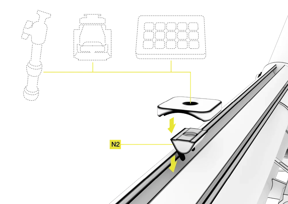
| NOTE: The Mounting Plates (M) and T-nuts (N2, N3) are used for mounting 3rd party accessories. Installation process is covered in the MOUNTING OPTIONAL THIRD-PARTY ACCESSORIES section. |
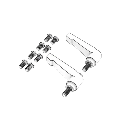
INSTALLING THE CAM LEVER CLAMPS
| TIP: Undoing the cam levers will allow you to adjust the position of the shifter plate longitudinally. |
To complete the step, the following hardware will be used:
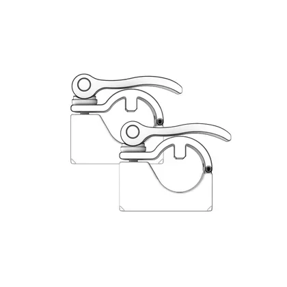
Cam Lever Clamps (2x)
- Unscrew the cam levers and open the clamps.
- Insert the locating pin on the bottom half of the clamps into the groove on the underside of the Shifter Mount Tube.
- Move the clamps to the desired position. Make sure the distance between both clamps matches the width of the Shifter Mounting Plate.
- Carefully tighten the cam levers by rotating them clockwise until there is enough pressure to securely lock the clamp in place. Do not overtighten the cam levers.
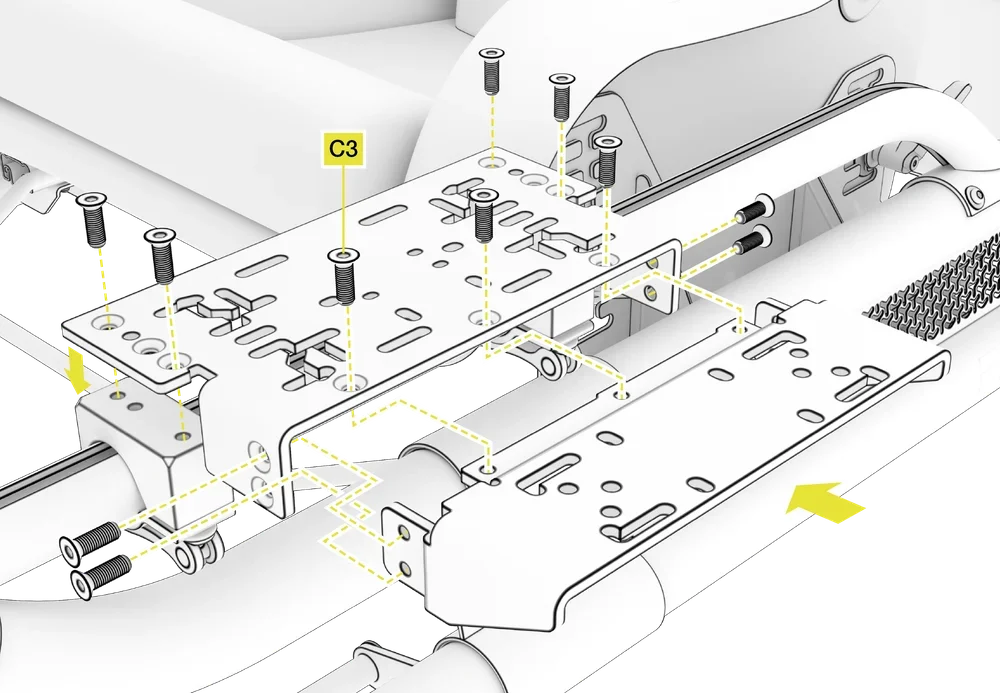
INSTALLING THE SHIFTER AND HANDBRAKE MOUNTING PLATES
Open the hardware bag labeled SHIFTER (PLATE).
To complete the step, the following hardware and tools will be used:
M6 Allen Key
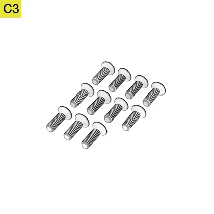
M6 12mm Countersunk Bolts (11x)
Shifter Mounting Plate
- Place the larger Shifter Mounting Plate over the clamping blocks.
- Secure the Shifter Mounting Plate to the clamps by screwing in four M6 12mm Countersunk Bolts (C3).
Handbrake Mounting Plate
- Slide the smaller handbrake mounting plate into the Shifter Mounting Plate.
- Secure the handbrake mounting plate to the Shifter Mounting Plate by screwing in seven M6 12mm Countersunk Bolts (C3).
OPTIONAL: INSTALLING THE KEYBOARD TRAY ASSEMBLY
| NOTE: The Keyboard Tray requires at least one Shifter Mounting Kit in order to fit it to your cockpit. |
The keyboard tray requires some assembly prior to installing it to your cockpit.
The included hardware bags labeled KEYBOARD TRAY SPARE PARTS and KEYBOARD TRAY contain a set of allen keys and spare bolts for reconfiguring your keyboard tray accessory to attach other products to the VESA Mount.
To complete the step, the following tools will be used:
M4 Allen Key
M8 Allen Key
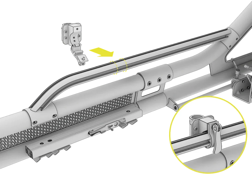
1: ATTACHING THE CLAMPING BLOCKS
- Determine where on the Shifter Mounting Tube you would like to install your optional Keyboard Tray.
- Lift the cam lever of the Clamping Block and unscrew it. Open the clamp and place it over the Shifter Mounting Tube so that the locating pin of the clamp catches the inner groove of the tube.
- Ensure the hinge section of the Clamping Block is on the underside of the Shifter Mounting Tube.
- Close the clamp by inserting it through the smaller hinged section of the Clamping Block.
- Re-screw the cam-lever until it is sufficiently tightened to lock the cam-lever in place when in its closed position. Do not overtighten cam levers of the clamps.
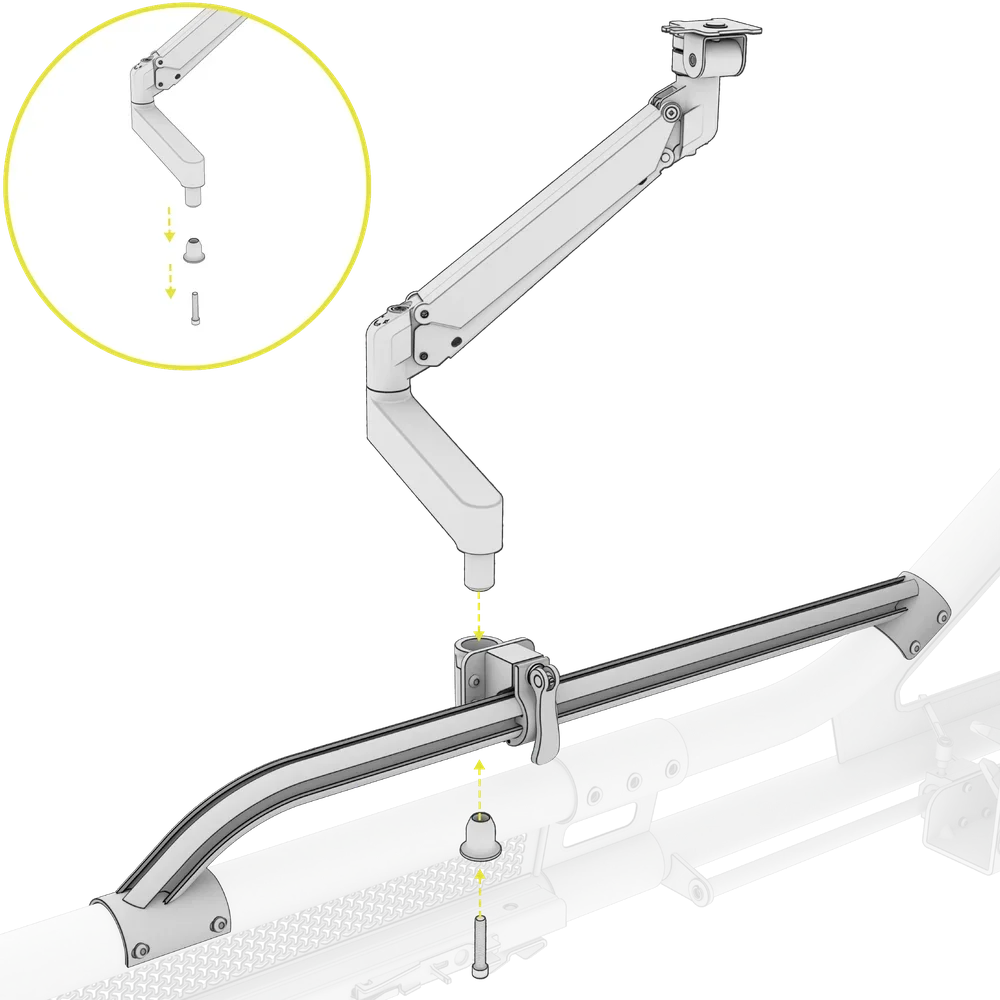
2: ATTACHING THE ARTICULATING ARM
- Using the M8 Allen Key, remove the locking bolt and holder from the underside of the Articulating Arm.
- Insert the end of the Articulating Arm into the already positioned Clamping Block.
- Reinsert the holder and the locking bolt and secure tightly.
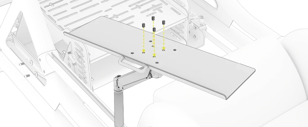
3: ATTACHING THE KEYBOARD TRAY
1. Using the M4 Allen Key, loosen the four set screws in the center of the Keyboard Tray.

2. Position the tray over the Mounting Plate of the upper section of the Articulating Arm.
3. Slide the Keyboard Tray over the Mounting Plate, ensuring the orientation of the tray matches the image below.

4. Rotate the locking pin that secures the tray on the mount and tighten the four set screws to secure the tray.
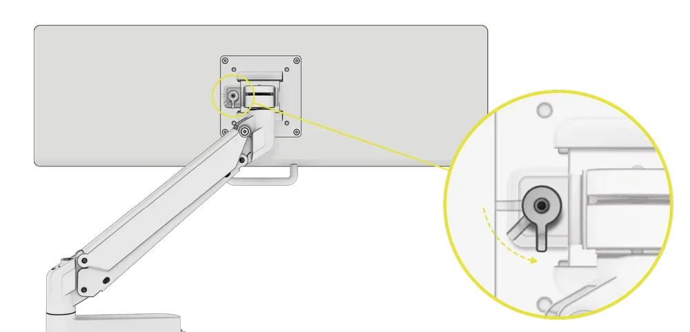
| IMPORTANT: To avoid damage to your keyboard or mouse ensure the set screws are flush with the upper surface of the Keyboard Tray. |
|
NOTE:
|
OPTIONAL: INSTALLING THE FRONT MOUNT BRACKET ASSEMBLY
| NOTE: In order to install the front mount bracket assembly, the main wheelbase mounting plate (17) from step 10B will need to be uninstalled. |
To complete the step, the following hardware and tools from step 10B will be used:
M8 Allen Key
M6 Allen Key
M8 20mm L-Bolts (2x)
M8 Spring Washers (2x)
M8 Washers (4x)
M6 Shoulder Bolts (2x)
Locking Pin (1x)
- Remove the existing main Wheelbase Mounting Plate (17). Refer to step 10B.
- Attach the front mount bracket assembly to the Right and Left Steering Mount Brackets (15, 16) by using one M6 Shoulder Bolt (S4), one M8 Washer (W2) and one M8 spring Washer (W5) on each side. Do not overtighten the shoulder bolts.
- Screw in the spring loaded Locking Pin Bolt (P2) through the Left Steering Mount Bracket (16) and the left side of the front mount bracket assembly.
- Screw the two M8 20mm L-Bolts (S6) and two M8 Washers (W2) through the steering mount brackets and into the front mount bracket assembly on each side.
- To adjust the wheelbase tilt, loosen both L-Bolts (S6), release the Locking Pin (P2) by pulling it outwards, and rotate the plate upwards or downwards. Make sure you retighten the L-Bolts (S6) once you have adjusted the tilt.
| NOTE: To change the height of the assembly, undo the eight M5 16mm Bolts (B2), eight M5 Washers (W1) and eight M5 Spring Washers (W4) that secure the Right and Left Steering Mount Brackets (15, 16), covered in step 10A. Reposition the assembly with the brackets attached to a desired height and re-secure them using the same hardware. |
OPTIONAL: INSTALLING THE LEFT AND RIGHT UPPER ACCESSORY MOUNTS
Open the hardware bag labeled UPPER ACCESSORY (TUBE).
To complete the step, the following hardware and tools will be used:
M6 Allen Key
M6 12mm Bolts (4x)
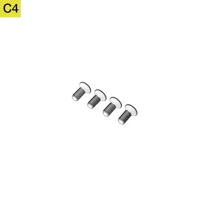
M6 20mm Countersunk Bolts (4x)
M6 Curved Washers (4x)
M6 T-Nuts (4x)
1/4 Inch 20 T-Nuts (4x)

Mounting Plates (8x)
| NOTE: The Mounting Plates (M) and T-Nuts (N2, N3) are used for installing third-party accessories. Installation process is covered in the INSTALLING OPTIONAL THIRD-PARTY ACCESSORIES section. |
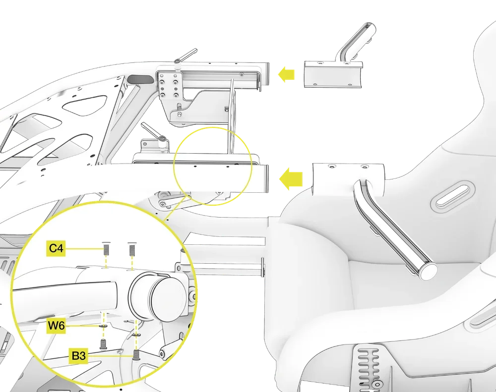
- Carefully slide the optional Upper Accessory Mounts over the steering tubes on the left and right sides of the frame.
- Secure the mounts by screwing in two M6 20mm Countersunk Bolts (C4) to the upper side and two M6 12mm Bolts (B3) with two M6 20mm curved washers (W6) to the underside. The concave side of the curved washer must face the frame.
- Repeat the process for the opposite side of the frame.
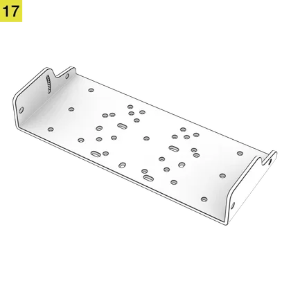
OPTIONAL: INSTALLING THE ACCESSORY PC TRAY
| CAUTION: Do not under any circumstances try to lift the front of your cockpit using the installed PC Tray. Securely tighten all nuts and bolts prior to use. |
Open the hardware bag labeled PC TRAY.
To complete the step, the following hardware and tools will be used:
M6 Allen Key
M6 Open-ended Wrench

M6 15mm Bolts (4x)

M6 20mm Countersunk Bolts (8x)
M6 Flange Nut (12x)
1. Remove the two lowest M6 12mm Bolts (B3) from the Top Panel (10).
2. Position the main PC Tray over the holes in the Top Panel (10) and hold it securely while you screw back in the two previously removed M6 12mm Bolts (B3). Do not release the tray until it is fully secured.

3. Secure the right-side supporting bracket to the main PC Tray with two M6 15mm Bolts (B4) and two M6 Flange Nuts (N4).
4. Repeat the process for the left-side supporting bracket.
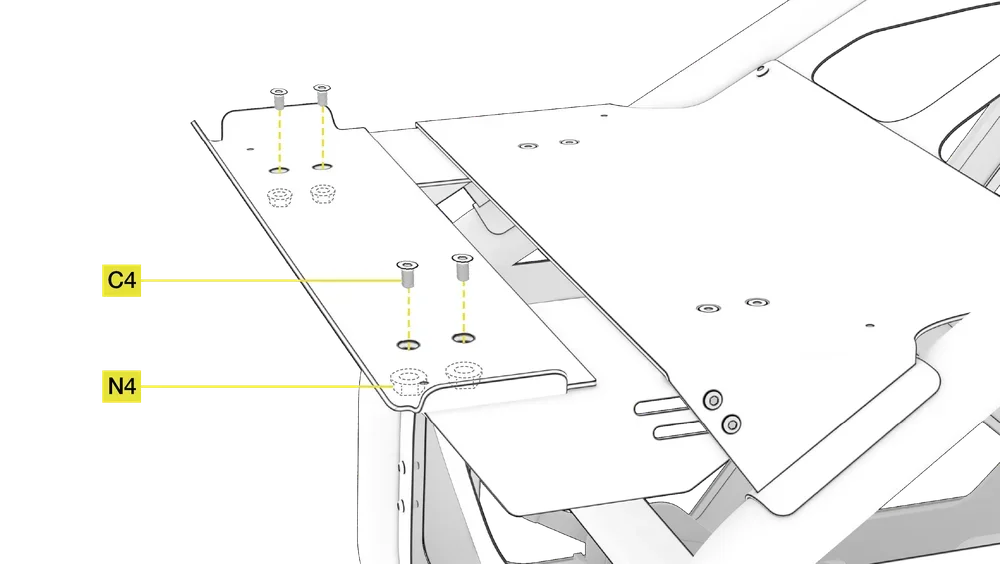
5. Secure the front section to the attached left and right supporting brackets with four M6 20mm Countersunk Bolts (C4) and four M6 Flange Nuts (N4).
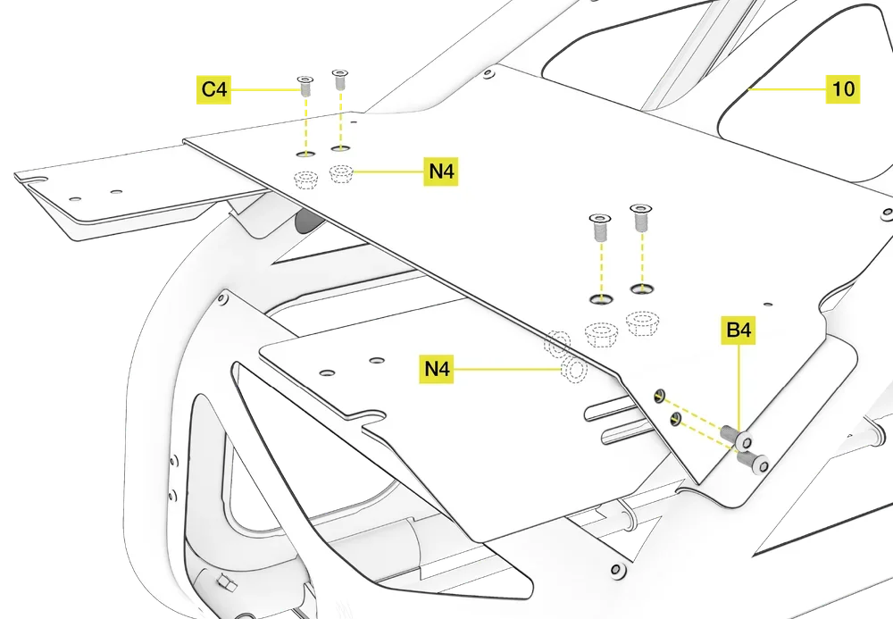
6. Use the remaining four M6 20mm Countersunk Bolts (C4) and four M6 Flange Nuts (N4) to additionally secure the main tray to the supporting brackets.
ADJUSTING THE PC TRAY WIDTH
To complete the step, the following tool will be used:
In order to accommodate a larger PC case, the depth of the PC Tray can be adjusted:
- Loosen the four M6 15mm Bolts (B4) and four M6 Flange Nuts (N4) on the left and right side of the PC Tray.
- Loosen the four M6 20mm Countersunk Bolts (C4) and four M6 Flange Nuts (N4) on the top of the PC Tray.
- Adjust the PC Tray outwards to your desired position, and retighten all 8 bolts before placing your computer or console onto the PC Tray.

OPTIONAL: INSTALLING THE INVERTED PEDAL BRACKETS
Open the hardware bag labeled INVERTED PEDAL BRACKETS.
To complete the step, the following hardware and tools will be used:
M8 20mm L-Bolts (4x)
M8 Washers (4x)

7mm Grommets (2x)
| NOTE: The two 7mm Grommets (G) are used for the formula styled pedal mounting position. The installation process is covered in the SETUP AND ADJUSTMENT SUGGESTIONS section below. |
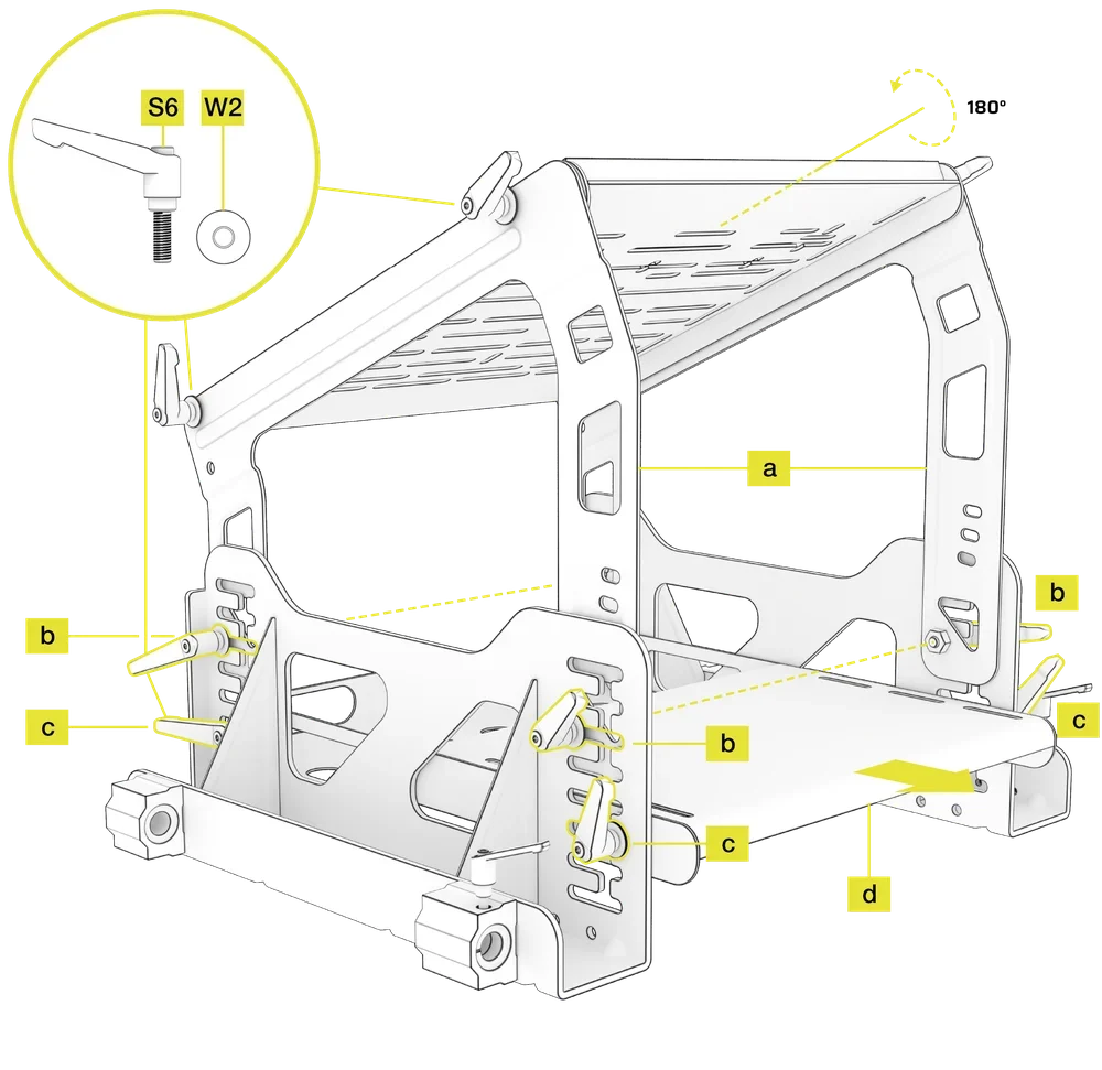
- Remove the upper pedal mounting plate and rotate it 180° on its axis. The upper side of the plate should now be facing down.
- For ease of installation, we suggest attaching the brackets to the now inverted upper pedal plate outside the cockpit.
- Secure the upper pedal mounting plate to the inverted brackets by using the four M8 20mm L-Bolts (S6) and four M8 Washers (W2).
- Place the assembly between the pedal side brackets, determine the required mounting height relative to your pedal set and secure it by using the existing four M8 20mm L-Bolts (S6) and four M8 Washers (W2).
- Adjust the lower heel rest / powerbrick holder to your desired height and secure it by using the existing four M8 20mm L-Bolts (S6) and four M8 Washers (W2).
| TIP: You can use the extra holes in the inverted brackets to create a higher undermounted pedal placement to facilitate an open wheel type seating position. Refer to the SETUP AND ADJUSTMENT SUGGESTIONS section below for optimal configuration of your setup. |
OPTIONAL: INSTALLING THIRD-PARTY ACCESSORIES
ADDING THE T-NUTS TO THE ACCESSORY RAILS
To complete the step, the following hardware and tools from step 10A will be used:
M5 Allen Key
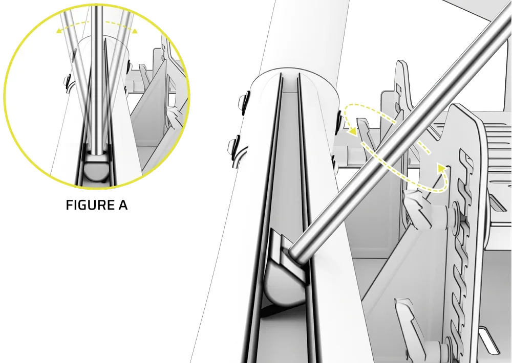
- Insert the T-Nuts (N2, N3) into the channel with Spring Plates on their undersides.
- Insert the Allen Key and apply slight pressure. Gently rotate the Allen Key in the direction of the arrow.
- Rock the Allen Key back and forth until each T-Nut (N2, N3) is seated correctly. See FIGURE A.
| TIP: T-Nuts (N2, N3) can be positioned on both the upper accessory mounts, as well as the Shifter Mounting Tubes. Darker colored T-Nuts have a 1/4 inch thread (N2) while lighter colored, silver T-Nuts have a M6 thread (N3). |
INSTALLING THIRD-PARTY ACCESSORIES
To complete the step, the following hardware and tools from the step OPTIONAL: INSTALLING THE LEFT AND RIGHT UPPER ACCESSORY MOUNTS will be used:
Mounting Plates (8x)
M6 T-Nuts (4x)
1/4 Inch 20 T-Nuts (4x)
You can add third-party accessories such as Elgato products and streaming equipment to your Fanatec ClubSport GT racing cockpit. Additional third-party mounting hardware may be used with M6 and 1/4 inch threaded T-Nuts (N2).
SETUP AND ADJUSTMENT SUGGESTIONS
PEDAL MOUNT ASSEMBLY SUGGESTED ADJUSTMENT
- Place the left and right inverted pedal mounting brackets on the inside of the side pedal brackets (a).
- Mount the pedal mounting brackets to the third slot from the top of the side bracket (b).
- Mount the Heel Plate to the third slot from the bottom of the side bracket (c).
- For extra heel space, slide the Heel Plate all the way towards the driver and secure it with the L-Bolts (d).
FORMULA STYLE PEDAL MOUNT ASSEMBLY SUGGESTED ADJUSTMENT
To complete the step, the following hardware from step OPTIONAL: INSTALLING THE INVERTED PEDAL BRACKETS will be used:
7mm Grommets (2x)
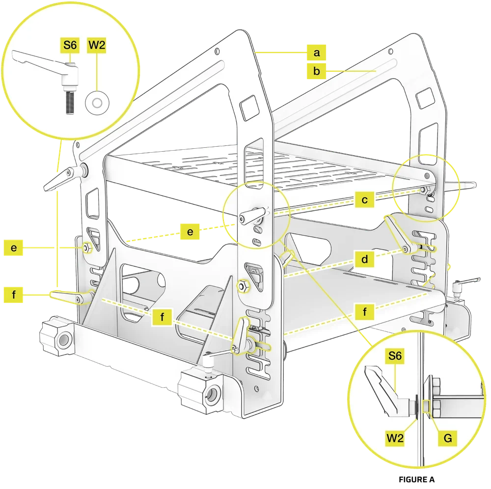
- Place the left side inverted pedal mounting bracket on the outside of the right side pedal bracket (a).
- Place the right side inverted pedal mounting bracket on the outside of the left side pedal bracket (b).
- Place the 7mm Grommets (G) between the inverted brackets and pedal slide plates. Secure the brackets at height shown in the image using four M8 20mm L-Bolts (S6) and four M8 Washers (W2) (c). See FIGURE A.
- Position the front (driver side) of the pedal mounting brackets to the second slot from the top of the side bracket. Secure the brackets using four M8 20mm L-Bolts (S6) and four M8 washers (W2) from the inside (d).
- Position the rear of the pedal mounting brackets to the third slot from the top of the side bracket. Secure the brackets using four M8 20mm L-Bolts (S6) and four M8 washers (W2) from the inside (e).
- Position the Heel Plate to the third slot from the bottom of the side bracket (f).
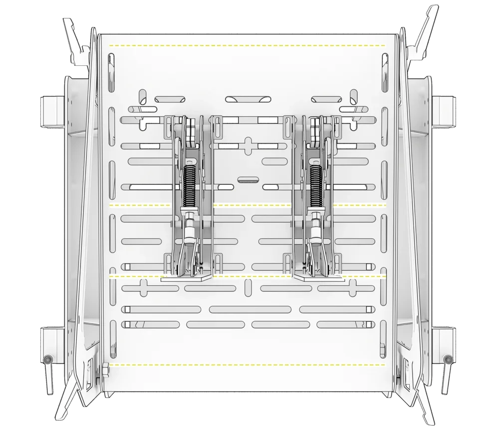
POSITIONING SEPARATE THIRD-PARTY PEDALS ON THE PEDAL MOUNTING PLATE
We suggest mounting your OEM separate pedals over the yellow marked strengthening ribs located on the underside of the pedal plate.
SUGGESTED SEAT / PEDAL ADJUSTMENT FOR MULTIPLE DRIVING POSITIONS
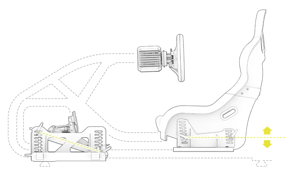
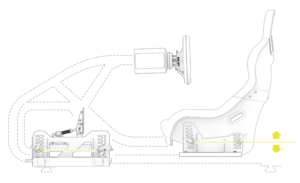
RALLY STYLE – FANATEC CSL-DD / CS-DD AND CS V3 PEDALS
For an upright rally style position, we suggest mounting your seat parallel with the horizontal slots in the seat mounting brackets. To increase the seat height, raise the seat, counting an equal number of slots, front and rear. Position the pedal plate as suggested in the image below.
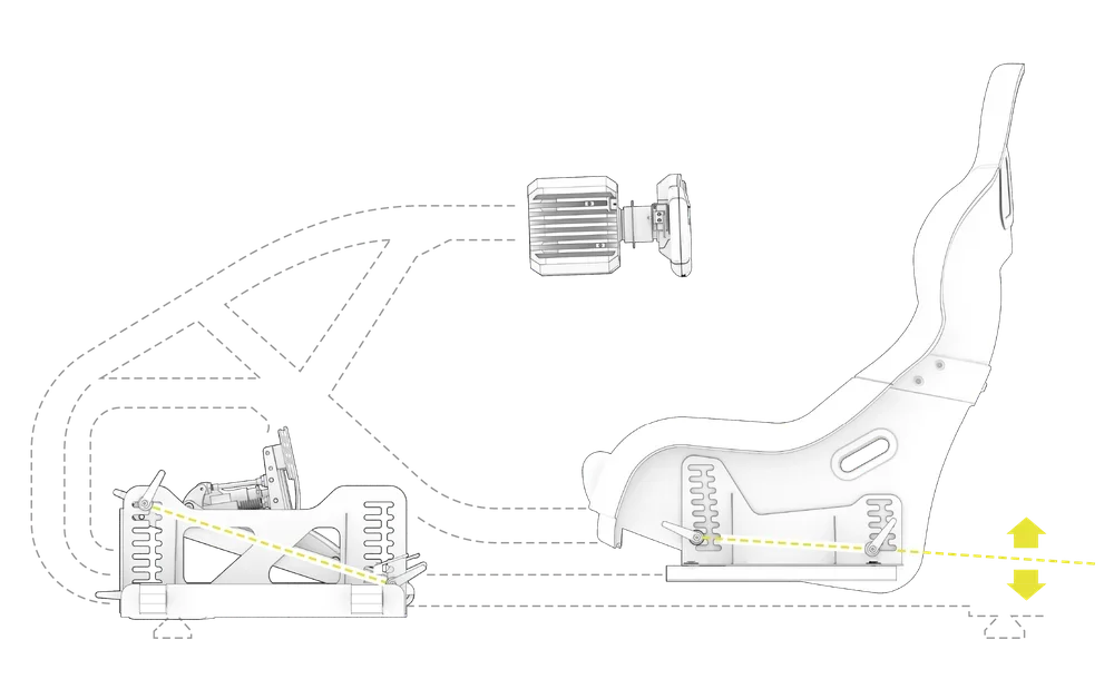
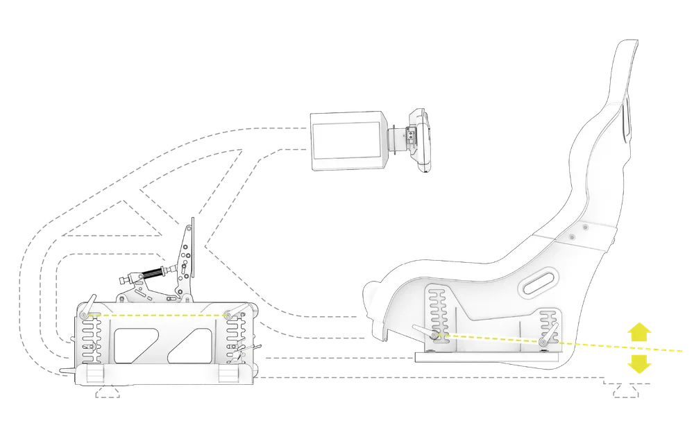
GT STYLE - FANATEC CSL-DD / CS-DD AND CS V3 PEDALS
For a GT style position, we suggest mounting your seat so that the front is 1-2 slots higher than the rear. To increase the seat height, raise the seat, counting an equal number of slots, front and rear. Position the pedal plate as suggested in the image below.
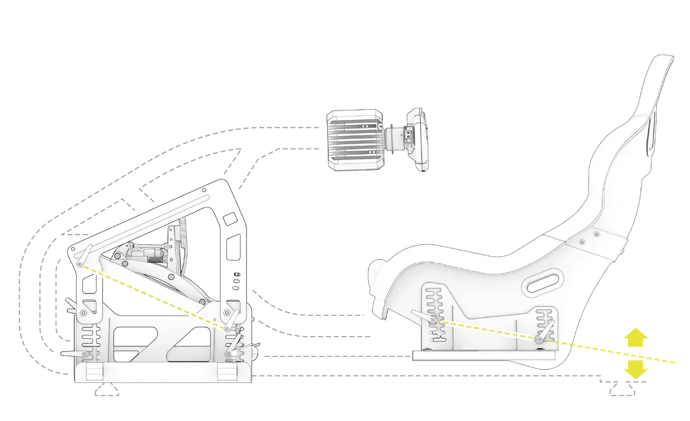
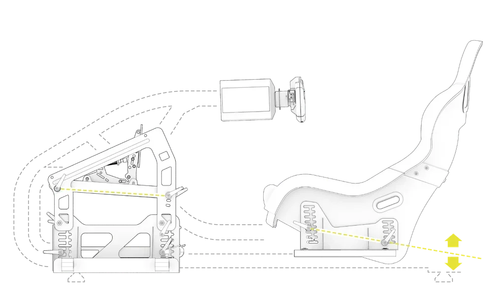
FORMULA STYLE - FANATEC CSL-DD / CS-DD AND CS V3 PEDALS
For a formula style position, we suggest mounting your seat so that the front is 3 slots higher than the rear. To increase the seat height, raise the seat, counting an equal number of slots, front and rear. Position the pedal plate as suggested in the image below.
RALLY STYLE – THIRD-PARTY PERIPHERALS
For an upright rally style position, we suggest mounting your seat parallel with the horizontal slots in the seat mounting brackets. To increase the seat height, raise the seat, counting an equal number of slots, front and rear. Position the pedal plate as suggested in the image below.
GT STYLE – THIRD-PARTY PERIPHERALS
For a GT style position, we suggest mounting your seat so that the front is 1-2 slots higher than the rear. To increase the seat height, raise the seat, counting an equal number of slots, front and rear. Position the pedal plate as suggested in the image below.
GT STYLE + INVERTED PEDAL MOUNT – THIRD-PARTY PERIPHERALS
For a GT style position, we suggest mounting your seat so that the front is 1-2 slots higher than the rear. To increase the seat height, raise the seat, counting an equal number of slots, front and rear. Position the pedal plate as suggested in the image below.

FORMULA STYLE – THIRD-PARTY PERIPHERALS
For a formula style position, we suggest mounting your seat so that the front is 3 slots higher than the rear. To increase the seat height, raise the seat, counting an equal number of slots, front and rear. Position the pedal plate as suggested in the image below.
STICKER POSITIONS
To complete the step, the following hardware from the STICKER & VELCRO bag will be used:
Four-color Arrow Labels (8x)
Using the labels is a quick and easy way to save time when adjusting your cockpit for multiple drivers:
- Use the etchings found on the main frame to place your removable stickers for quick and easy driving position changes. Use different colored labels for multiple drivers.

CARE AND MAINTENANCE
Your Fanatec Clubsport GT cockpit is manufactured to be robust and sturdy during use. However, by following basic care and maintenance steps, you can improve the longevity and performance of your cockpit.
| IMPORTANT: This product is designed for adult use. We recommend adult supervision for any children using this product. |
- Before each use of your cockpit, ensure that all the bolts clamping the pedal assembly in place are secure.
- Routinely (at least once every two weeks) check the bolts securing the seat brackets, wheelbase, and pedals to ensure they are secure.
- To protect the finish of the cockpit, always sufficiently loosen the cam levers and bolts that secure all adjustable parts when using to prevent scraping or cosmetic damage.
- To protect the seat, do not place sharp or heavy items on the upholstered sections.
- To clean your cockpit, use a clean, dry microfiber cloth or a vacuum with a soft bristle attachment.
- Use caution when adjusting seating position to ensure the seat is positioned in the corresponding slots on either side of the seat, and the tracks are free from debris or fingers when sliding the seat.
- To protect your seat, do not place heavy items on the upholstered sections.
- Ensure a clutter-free environment before use and check to ensure cables are secure.
WARRANTY
All Fanatec racing cockpits have a 2-year warranty.
LEGAL
©2025 CORSAIR MEMORY, Inc. Trademarks belong to their respective owners. All rights reserved. Fanatec is a brand of CORSAIR MEMORY Inc.