MANUAL | QUICK START GUIDE
GT Cockpit Triple Monitor Expansion Kit (White)
Mounting Solutions for your Fanatec sim rig.
MONITOR SIZE RECOMMENDATIONS
| Single Monitor | Triple Screen Setup | Overhead Monitor | |
| Minimum Size | 32" | 32" | 27" |
| Maximum Size | 65" | 55" | 34" |
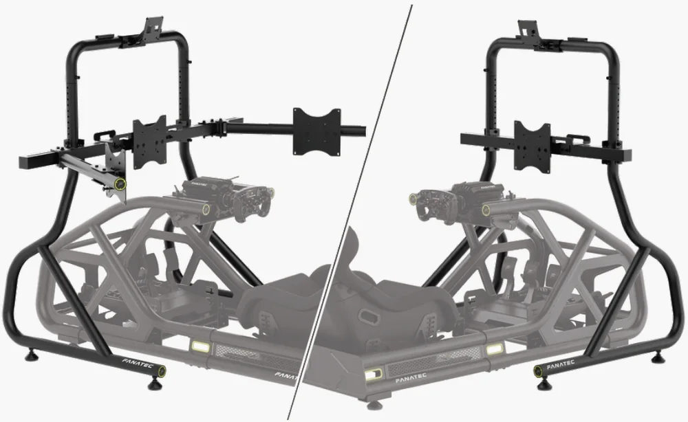
MONITOR STAND CONFIGURATIONS
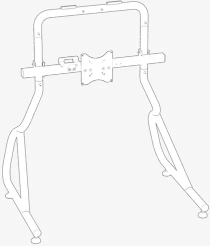
Single monitor stand
Suitable for use of a single monitor.
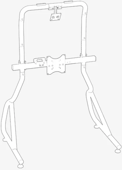
Single monitor stand with an additional overhead monitor - option A
Suitable for use of larger front and overhead monitors.
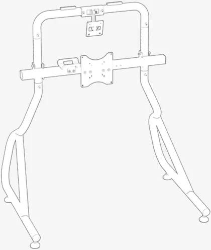
Single monitor stand with an additional overhead monitor - option B
Suitable for use of smaller front and overhead monitors.
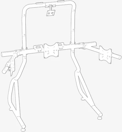
Triple screen expansion kit
Suitable for use of a front monitor with two additional monitors left and right.
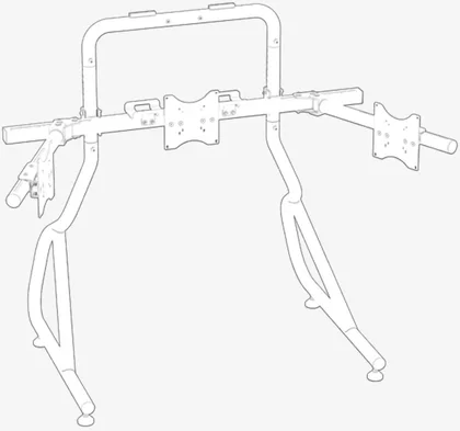
Triple screen expansion kit with an additional overhead monitor - option A
Suitable for use of larger front and overhead monitors, with two additional monitors left and right.
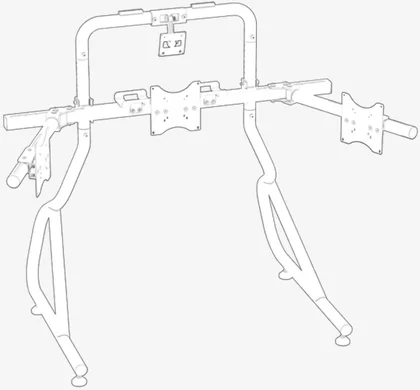
Triple screen expansion kit with an additional overhead monitor - option B
Suitable for use of smaller front and overhead monitors, with two additional monitors left and right.
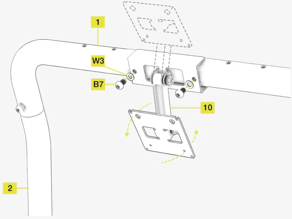
USING THE BEZEL FINE TUNING ADJUSTMENT MECHANISM
Vertical and rotation adjustment
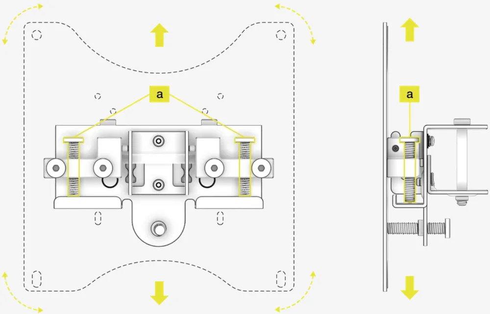
To rotate the screen, screw or unscrew the (a) bolts independently using the included M8 allen Key. Screwing the left (a) bolt will rotate the screen counterclockwise. Screwing the right (a) bolt will rotate the screen clockwise.
To raise or lower the screen, screw or unscrew both (a) bolts equally. Screwing the bolts in will raise the screen. Unscrewing the (a) bolts will lower the screen.
Lateral adjustment
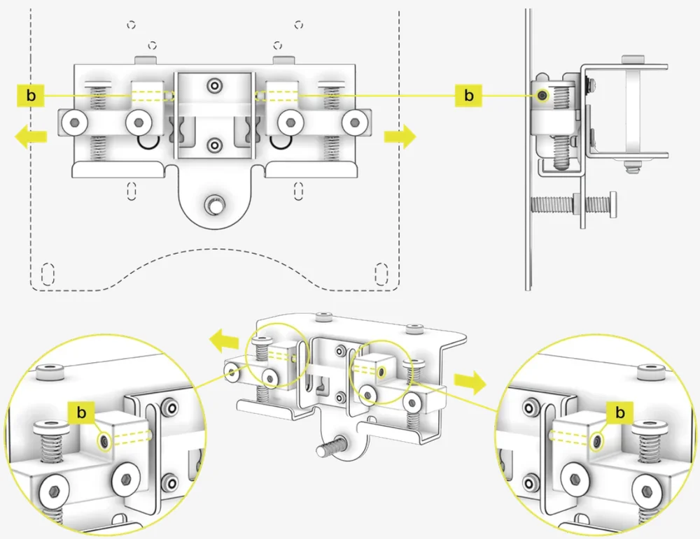
To adjust the horizontal position of the screen, loosen one of the (b) screws and tighten the (b) screw on the opposite side. Using the M4 allen key, you can adjust the lateral position by up to 11mm.
Tilt adjustment
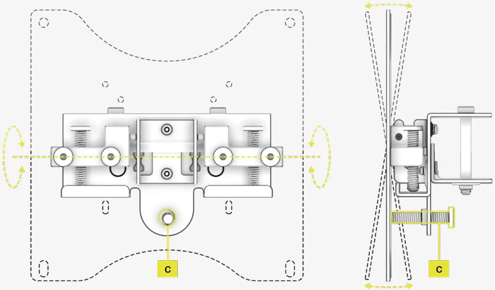
To tilt the screen forward or backward, screw in the (c) bolt using the included M8 Allen Key. Screwing the (c) bolt in will tilt the screen backward. Unscrewing the (c) bolt will tilt the screen forward.
SINGLE MONITOR STAND - INTRODUCTION
Congratulations on purchasing your new Fanatec Single Monitor Stand. It has been designed and engineered to pair elegantly with your Fanatec ClubSport sim racing cockpit.
Please take a moment to carefully read this guide prior to assembling your Fanatec Single Monitor Stand.
CAUTION: Your Single Monitor Stand is engineered from steel for strength and durability.
- Some of the components are heavy. Please exercise proper care when handling them.
- Ensure the chosen build area is clutter free and there is sufficient space for assembly.
- Use a soft floor covering, such as an old blanket or rug, to protect both the finish of your Single Monitor Stand and floor during assembly.
- To avoid stripping of threads, do not overtighten.
SINGLE MONITOR STAND - BOX CONTENTS
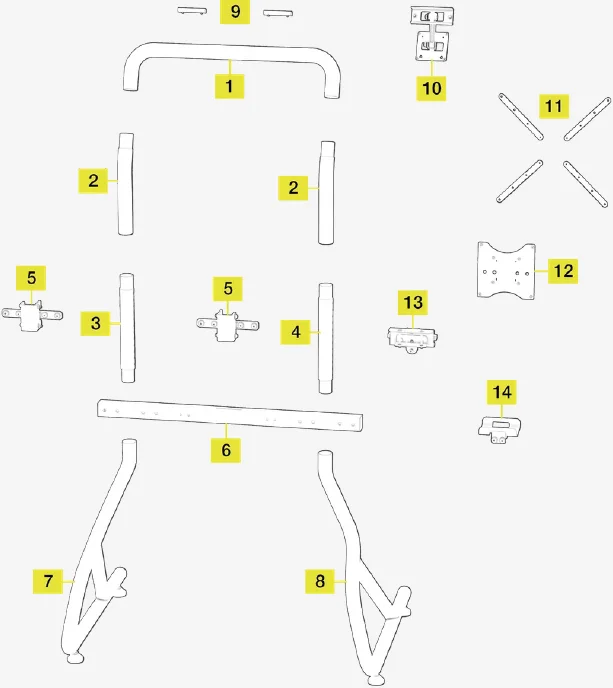
Single monitor stand - expanded view
Single monitor stand box contents
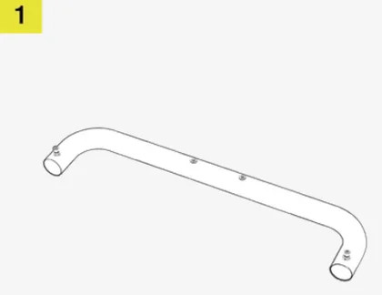
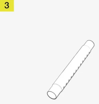
Top Main Frame Connecting Tube
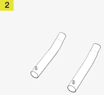
Left and Right Upper Monitor Mount Extension Tubes
Right Side Vertical Height Adjustment Tube

Left Side Vertical Height Adjustment Tube
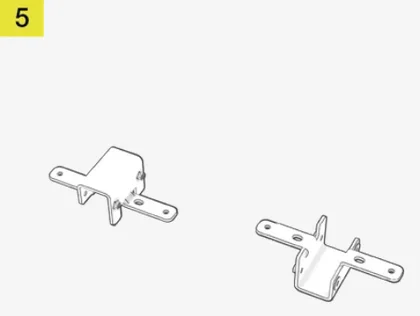
Left and Right Square Crossmember Mounting Brackets
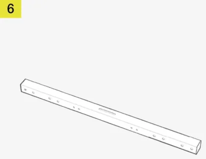
Main Square Tube Crossmember (1000mm)
Lower Right Main Frame
Lower Left Main Frame
Upper T-Rail Accessory Mounts (2x)
Upper VESA Mount Bracket
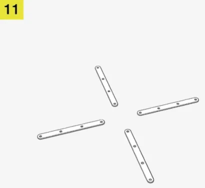
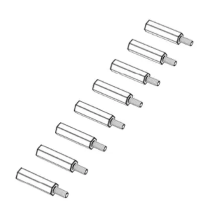
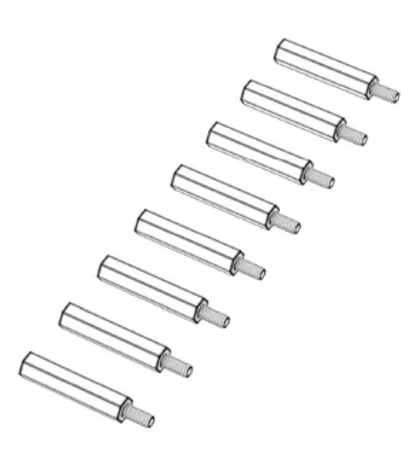
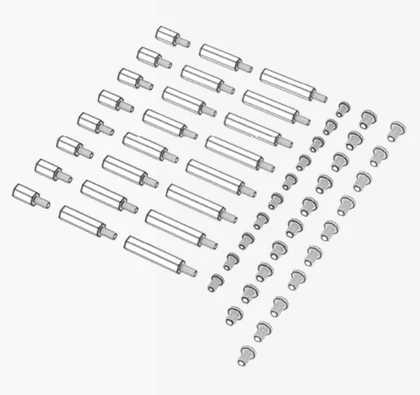
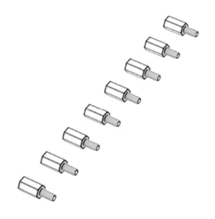
VESA Mount Extension Set
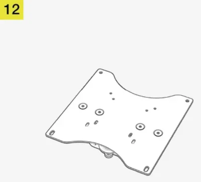
Main VESA Mount Plate
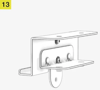
VESA Mount Fine Adjustment Bracket
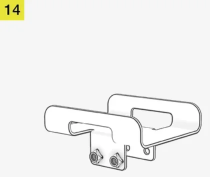
Power Brick Holder
Single monitor stand - included hardware
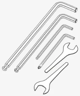
CS MS Tool Kit Bag:
- M4 Allen Key
- M6 Allen Key
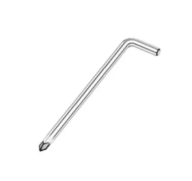
- M8 Allen Key
- M8 Open-ended Wrench
- M12 Open-ended Wrench
- Phillips Screwdriver
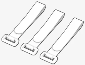
CS MS Velcro Bag:
- Velcro, Black (3x)
CS MS Velcro Bag:
- Velcro, White (3x)
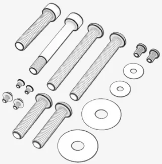
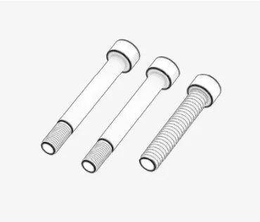
CS MS Spare Parts bag:
- M4 8mm Countersunk Bolts (2x)
- M4 10mm Bolts (2x)
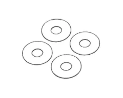
- M4 Washers (2x)
- M6 55mm Shoulder Bolt (1x)
- M8 12mm Bolts (2x)
- M8 25mm Bolts (2x)
- M8 50mm Bolts (1x)
- M8 75mm Bolts (2x)
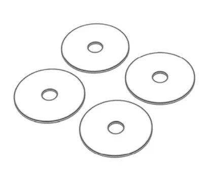
- M8 Washers (2x)
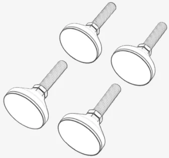
CS MS Step 1 Bag:
- M12 Rubber Feet (4x)
CS MS Step 2 Bag:
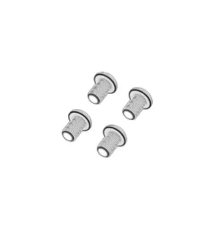
- M8 12mm Bolts (2x)
CS MS Step 3 Bag:
- M8 12mm Bolt (1x)
CS MS Step 4 Bag:
- M8 12mm Bolt (1x)
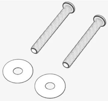
CS MS Step 5 Bag:
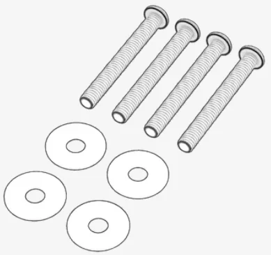
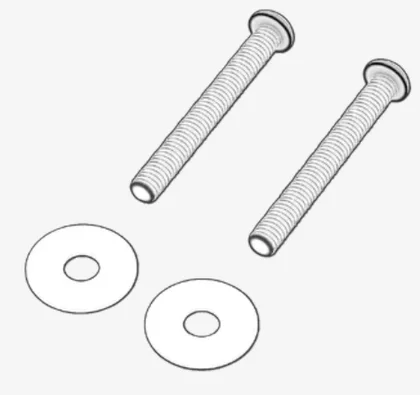
- M8 75mm Bolts (4x)
- M8 Washer (4x)
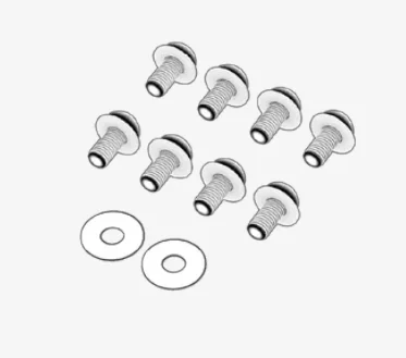
CS MS Step 6 Bag:
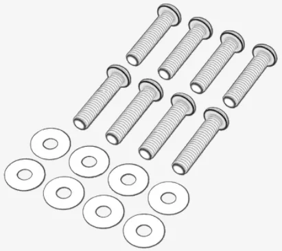
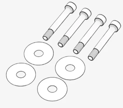
- M8 25mm Bolts (8x)
- M8 Washer (8x)
CS MS Step 7A Bag:
- M6 55mm Shoulder Bolts (2x)
- M8 50mm Bolt (1x)
CS MS Step 7C Bag:
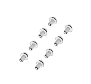
- M4 12mm Bolts (8x)
- M4 Washers (2x)
CS MS Step 8 Bag:
- M8 75mm Bolts (2x)
- M8 Washers (2x)
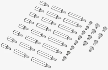
VESA Hardware bag:
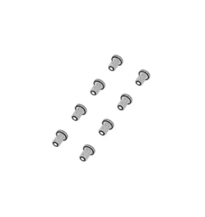
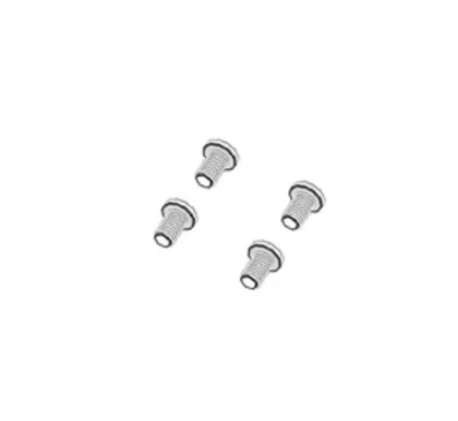
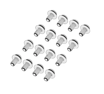
- M4 12mm Screws (8x)
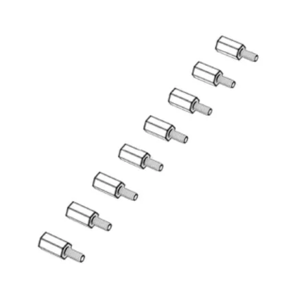
- M4 15mm Spacer Screws (8x)
- M4 30mm Spacer Screws (8x)
- M4 40mm Spacer Screws (8x)
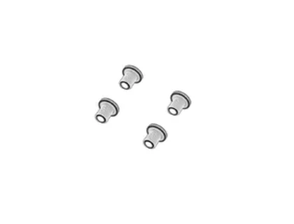
- M6 12mm Screws (4x)
- M6 16mm Screws (4x)
CS MS Upper Monitor Step 1A Bag:
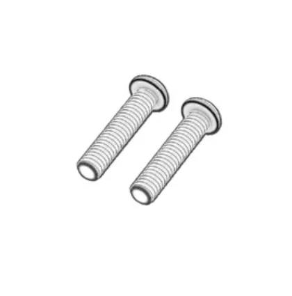
- M8 12mm Bolts (2x)
CS MS Upper Monitor Step 1B Bag:
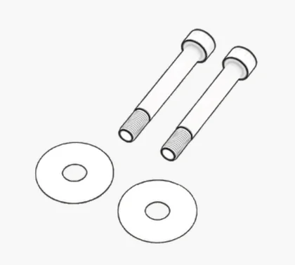
- M8 25mm Bolts (2x)
- M8 Washers (2x)
T-Rail Mounting Bolts Bag:
- M4 8mm Countersunk Bolts (4x)
SINGLE MONITOR STAND - ASSEMBLING
Please begin the assembly of your Fanatec Monitor Stand by unpacking the components from the box.
Follow the steps for assembly of the Monitor Stand laid out in this chapter.
1: Adding the adjustable feet
Open the tool and hardware bags labeled CS MS TOOL KIT and CS MS STEP 1.
To complete the step, the following hardware and tools will be used:
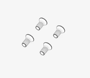
M12 Rubber Feet (4x)
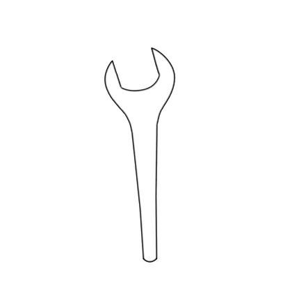
M12 Open-ended Wrench
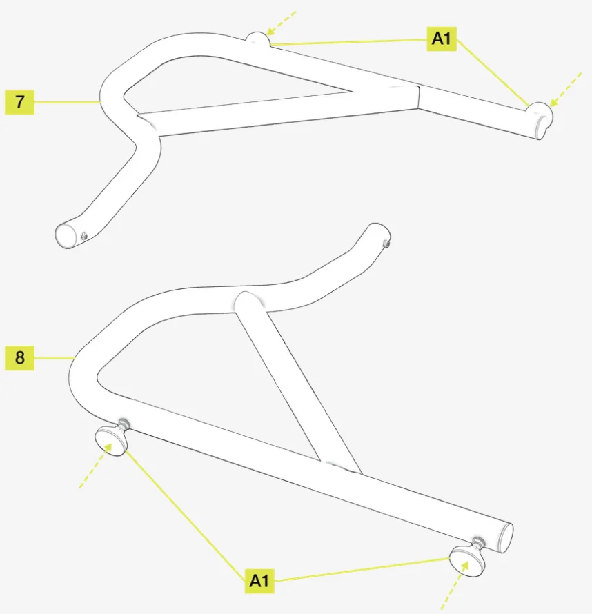
- Attach the Rubber Feet (A1) to each threaded hole on the underside of the Lower Right Main Frame (7) and Lower Left Main Frame (8). Screw the Rubber Feet (A1) all the way in until the locking nut makes contact with the underside of the lower main frame parts.
NOTE: Should there be too much resistance when screwing the feet into the frame, please use the suggested M12 Open-ended Wrench.
IMPORTANT: Do not overtighten any of the bolts in steps 2, 3 and 4.
NOTE: During steps 2, 3 and 4, place the parts on the floor with a soft covering or blanket underneath them. To avoid possible injury, excercise caution when sliding the tubular sections together. If possible, ask another person to help you steady the frame.
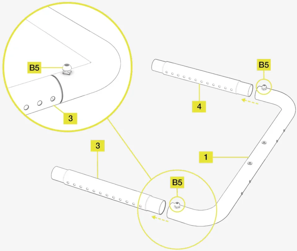
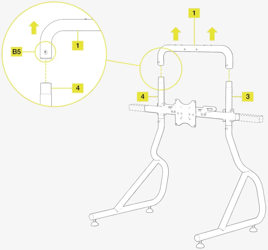
2: Assembling the top section of the main frame
Open the hardware bag labeled CS MS STEP 2.
To complete the step, the following hardware and tools will be used:
M8 Allen Key
M8 12mm Bolts (2x)
- Connect the Top Main Frame Connecting Tube (1) to the Left and Right Side Vertical Adjustment Tubes (4 and 3) by sliding them together. Ensure the adjustment holes are orientated as shown in the image below.
- Secure the tubes by screwing in two M8 12mm Bolts (B5).
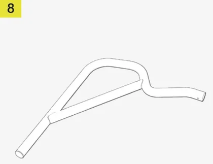
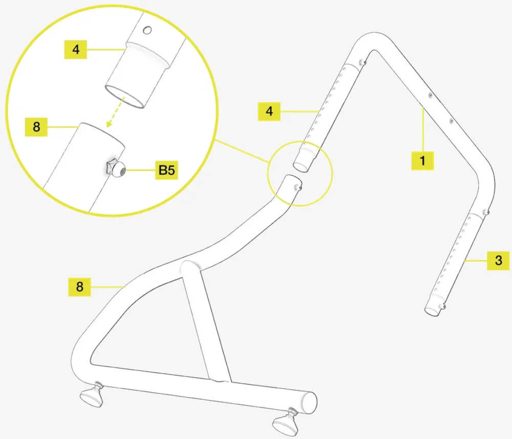
3: Attaching the left leg to the top section
Open the hardware bag labeled CS MS STEP 3.
To complete the step, the following hardware and tools will be used:
M8 Allen Key
M8 12mm Bolt (1x)
- Raise the upper part of the Lower Left Main Frame (8) so that the feet rest on the floor.
- Carefully slide the Left Side Vertical Height Adjustment Tube (4) of the assembled top section of the frame into the Lower Left Main Frame (8) as shown in the image below.
- Secure the tubes by screwing in the M8 12mm Bolt (B5).
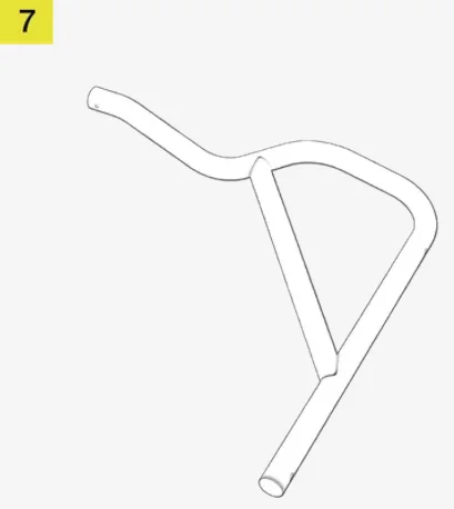
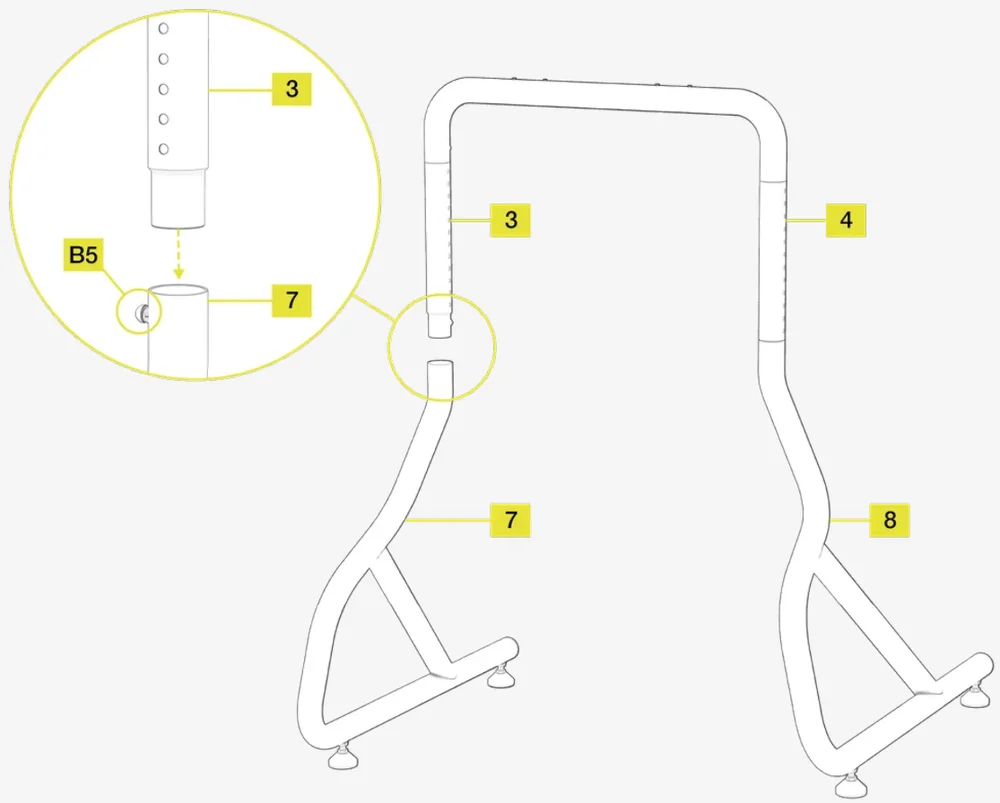
4: Attaching the right leg to the top section
Open the hardware bag labeled CS MS STEP 4.
To complete the step, the following hardware and tools will be used:
M8 Allen Key
M8 12mm Bolt (1x)
- Carefully raise the assembled sections from the floor and insert the Right Side Vertical Height Adjustment Tube (3) into the Lower Right Main Frame (7).
- Secure the tubes by screwing in the M8 12mm Bolt (B5).
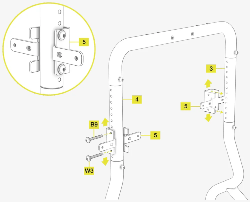
5: Attaching the square crossmember brackets
Open the hardware bag labeled CS MS STEP 5.
To complete the step, the following hardware and tools will be used:
M8 Allen Key
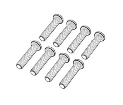
M8 75mm Bolts (4x)
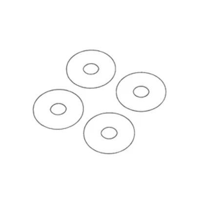
M8 Washers (4x)
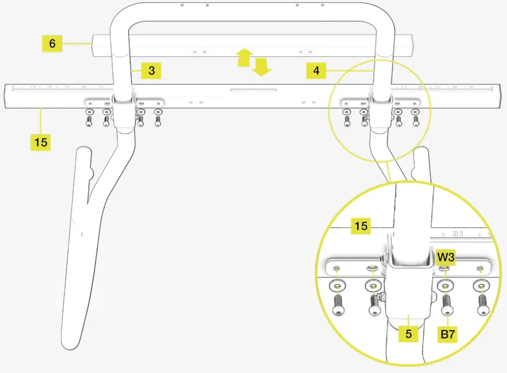
- Choose your desired monitor height setting on the Vertical Adjustment Tubes (3 and 4).
- Attach the Square Crossmember Mounting Brackets (5) to the Vertical Adjustment Tubes (3 and 4) and ensure the bolt holes on the bracket align with the holes on the tubes.
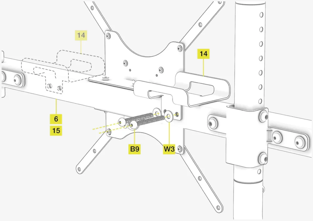
- Partially secure the brackets to the tubes by inserting four M8 75mm Bolts (B9) with four M8 Washers (W3).
IMPORTANT: Do not tighten the bolts until step 6.
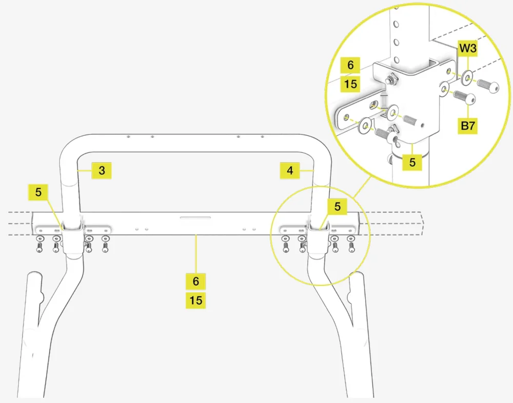
6: Attaching the main square tube crossmember
NOTE: The following step covers the installation of a 1000mm Crossmember (6) for the Single Monitor Stand. If you are assembling the Triple Screen Expansion Kit, substitute the 1000mm Crossmember (6) with the 1450mm Crossmember (15) from the Triple Screen Expansion Kit box.
Open the hardware bag labeled CS MS STEP 6.
To complete the step, the following hardware and tools will be used:
M8 Allen Key
M8 25mm Bolts (8x)
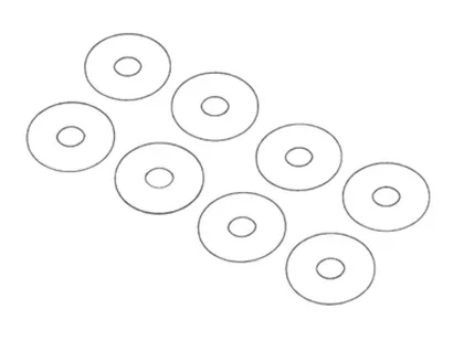
M8 Washers (8x)
- Insert the Main Square Tube Crossmember (6 or 15) into the Square Crossmember Mounting Brackets (5).
- Align the holes in the brackets with the holes in the crossmember.
- Secure the crossmember to the brackets by screwing in eight M8 25mm Bolts (B7) and eight M8 Washers (W3).
- Securely tighten all bolts from step 5 and step 6.
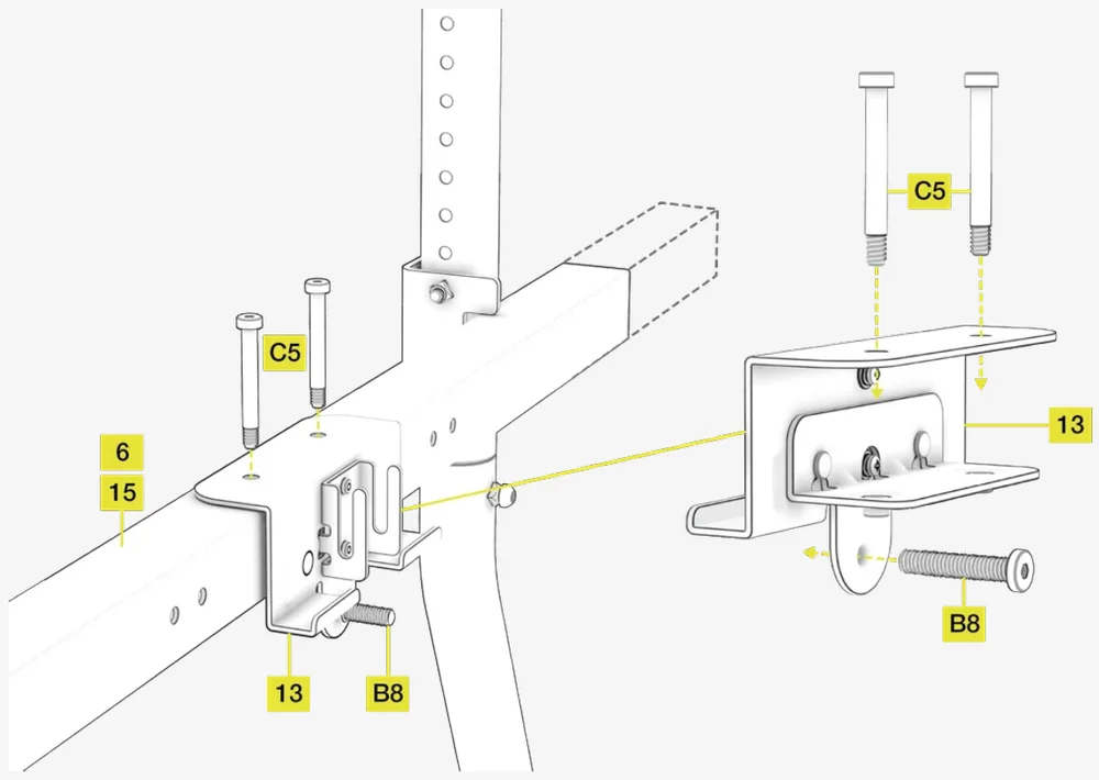
7A: Attaching the VESA mount bracket
Open the hardware bag labeled CS MS STEP 7A.
To complete the step, the following hardware and tools will be used:
M8 Allen Key
M8 50mm Bolt (1x)
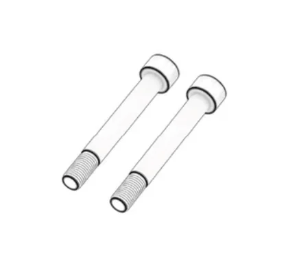
M6 55mm Shoulder Bolts (2x)
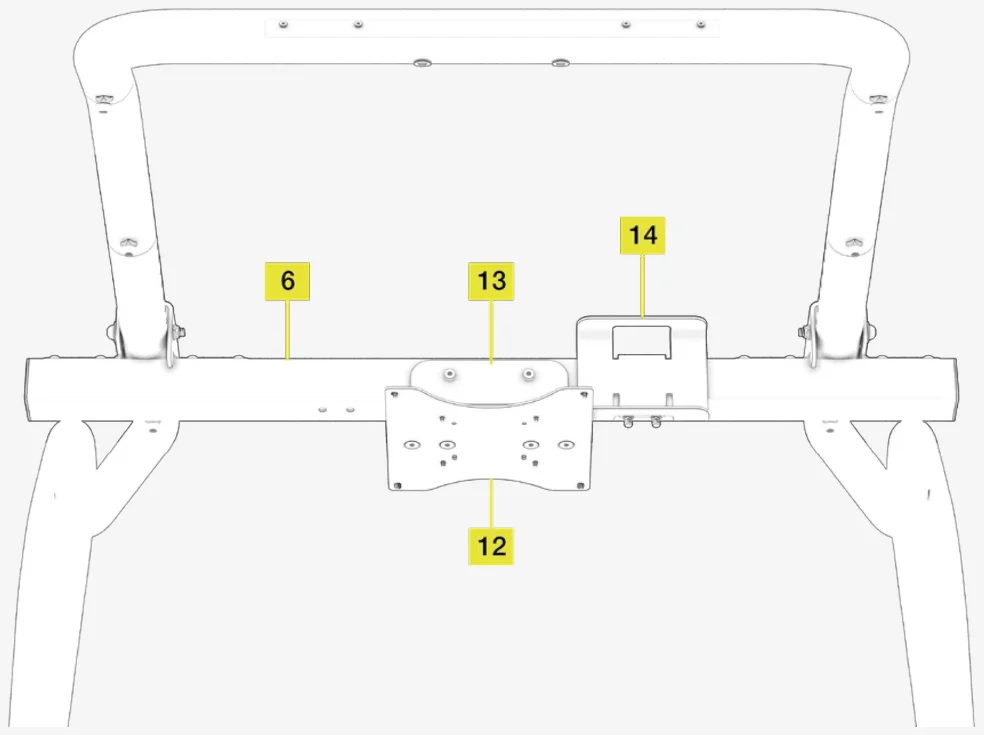
- Attach the VESA Mount Fine Adjustment Bracket (13) to the center of the Main Square Tube Crossmember (6 or 15).
- Align the holes in the bracket with the slot in the crossmember.
- Secure the bracket to the crossmember with two M6 55mm Shoulder Bolts (C5).
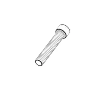
- Screw in M8 50mm Bolt (B8) through the bottom tab of the VESA Bracket (13) as shown in the image below.
7A-2: Mounting the monitor to the VESA plate
Open the hardware bag labeled VESA HARDWARE.
To complete the step, the following hardware and tools will be used:

M6 Allen Key

M4 Allen Key
M4 12mm Screws (8x)
M6 12mm Screws (4x)
M6 16mm Screws (4x)
M4 15mm Spacer Screws (8x)
M4 30mm Spacer Screws (8x)
M4 40mm Spacer Screws (8x)
NOTE: The included hardware is suitable for mounting monitors to both, the Main VESA Mount Plate (12) and the Upper VESA Mount Bracket (10), covered step 11.
NOTE: The included Main VESA Mount Plate (12) supports monitors with up to 200mm x 200mm VESA pattern on their rear panels. If you wish to mount a monitor with larger mount size pattern, please use the VESA Mount Extension Set (11), covered in step 7C.
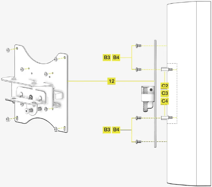
- Determine the size and depth of the VESA mount on the rear panel of your monitor. For recessed VESA mounts, use the appropriate included spacer screws (C2, C3, C4) and screw them into your monitor first.
- Attach the Main VESA Mount Plate (12) to the rear panel of your monitor and secure it by using appropriate bolts (B3, B4).
| VESA Pattern | Bolt size |
|
75mm x 75mm 100mm x 100mm 200mm x 100mm |
M4 12mm (B3) |
|
200mm x 200 mm ... or more |
M6 12mm / 16mm (B4) |
7B: Adding the main VESA mount plate
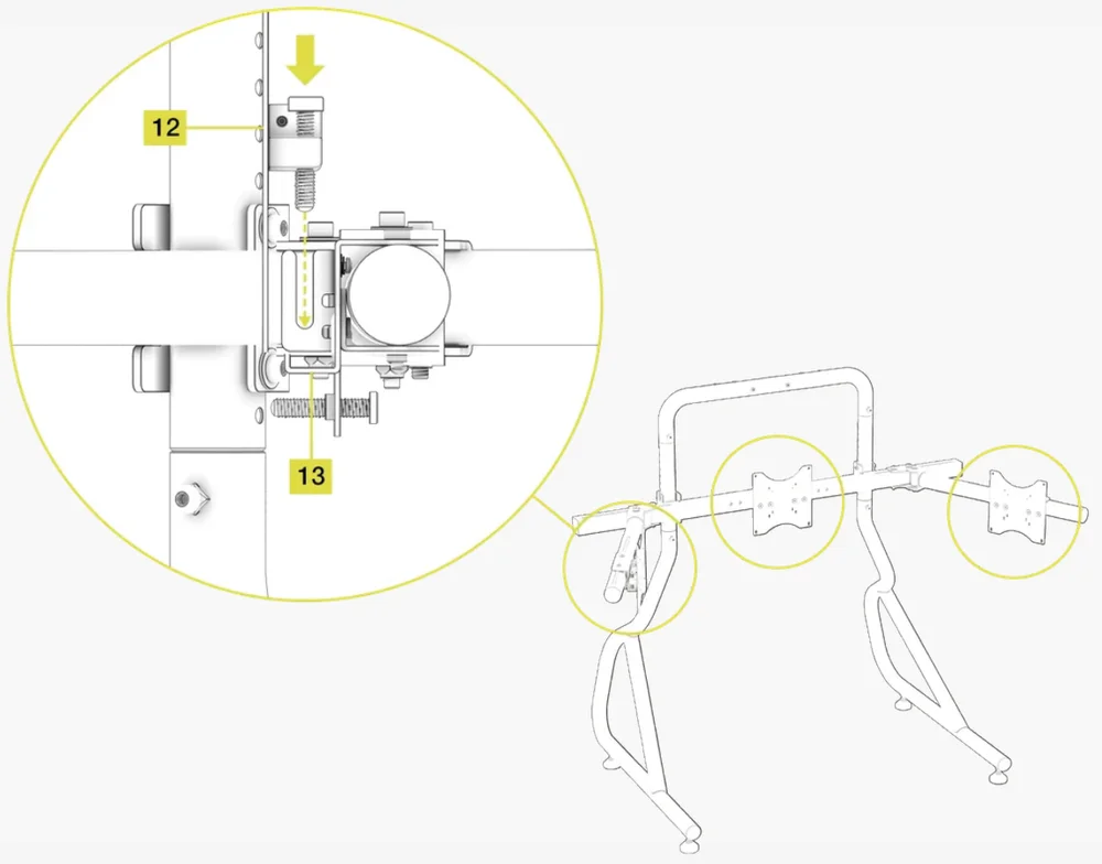
NOTE: The VESA mount includes a bezel fine tuning mechanism for aligning multiple bezels with each other. See chapter USING THE BEZEL FINE TUNING ADJUSTMENT MECHANISM in the beginning of this guide for a detailed explanation.
- Lower the Main VESA Mount Plate (12) into the slots in the VESA Mount Fine Adjustment Bracket (13). See FIGURE A. Ensure the fine tuning bolt heads on the Main VESA Mount Plate (12) are orientated upwards.
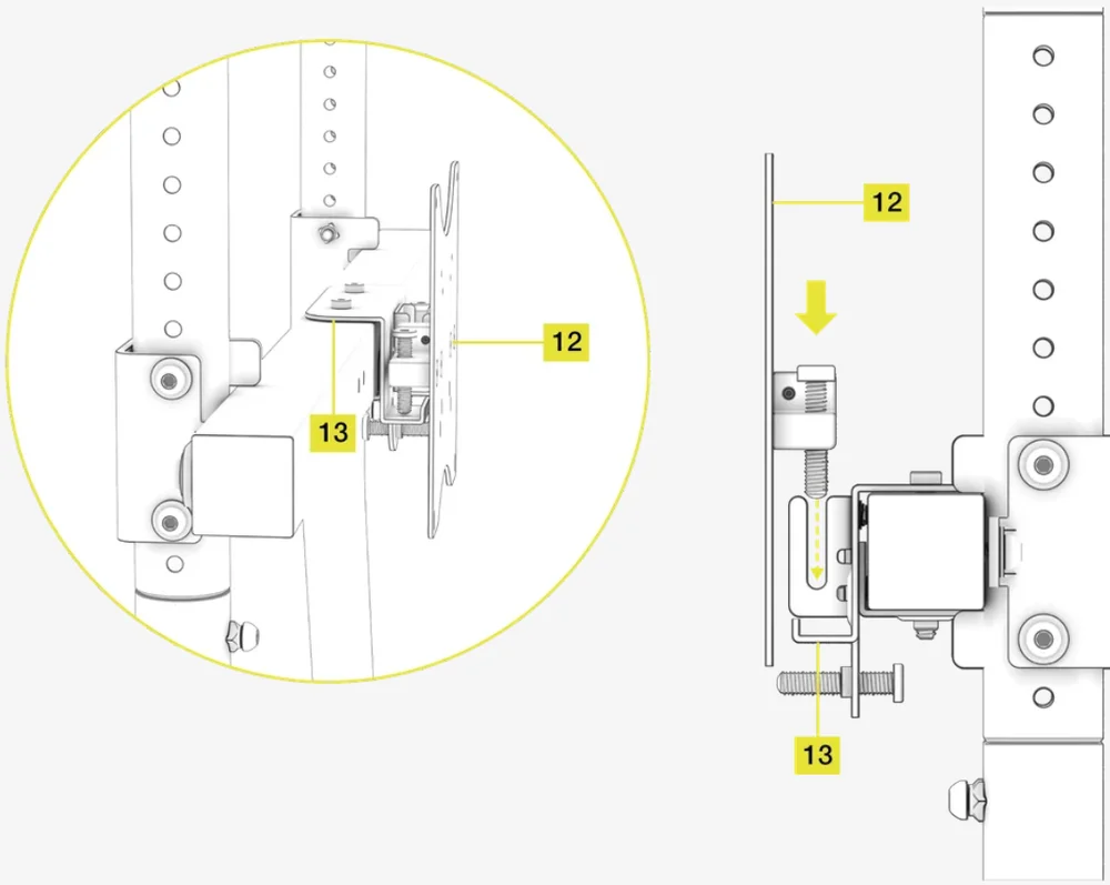
Figure A
7C: Attaching the included VESA mount extension set (optional)
NOTE: There are two additional VESA mount extension sets available in the Triple Screen Expansion Kit. The following installation process can also be used to install the additional extension sets.
Open the hardware bag labeled CS MS STEP 7C.
To complete the step, the following hardware and tools will be used:
Phillips Screwdriver
M4 12mm Bolts (8x)
M4 Washers (2x)
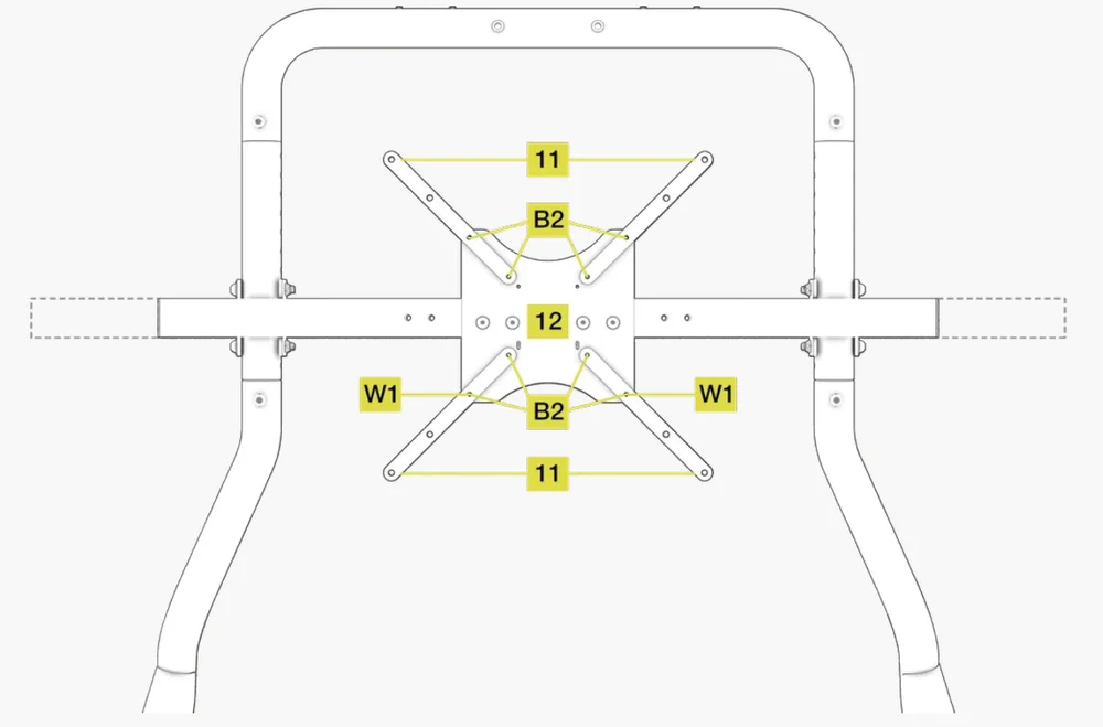
The included VESA Mount Extension Set (11) is used to mount monitors with VESA mounting pattern larger than 200x200mm.
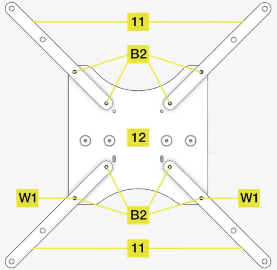
- Position the VESA Mount Extension Set (11) arms over the corresponding holes of the Main VESA Mount Plate (12).
- Secure the arms by screwing in eight M4 12mm Bolts (B3). Ensure that the bolts are inserted through the backside of the Main VESA Mount Plate (12).
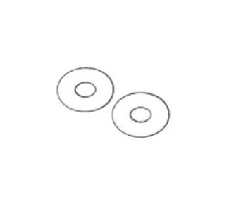
OPTIONAL: As an additional safety measure, you can use the two included M4 Washers (W1) on the two slotted holes on the bottom of the Main VESA Mount Plate (12).
NOTE: Image below shows a standard placement of the extension arms. Depending on your monitor size and VESA pattern, choose a suitable combination of mounting holes. Make sure the VESA mount is securely installed on your monitor before attaching it to the stand.
8: Attaching the included power brick holder accessory (optional)
NOTE: There is an additional Power Brick Holder available in the Triple Screen Expansion Kit. The following installation process can also be used to install the additional Power Brick Holder.
Open the hardware bag labeled CS MS STEP 8.
To complete the step, the following hardware and tools will be used:
M8 Allen Key
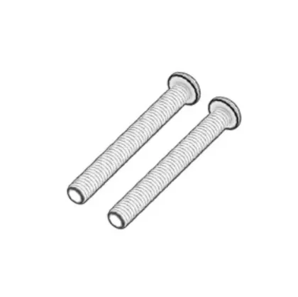
M8 75mm Bolts (2x)

M8 Washers (2x)
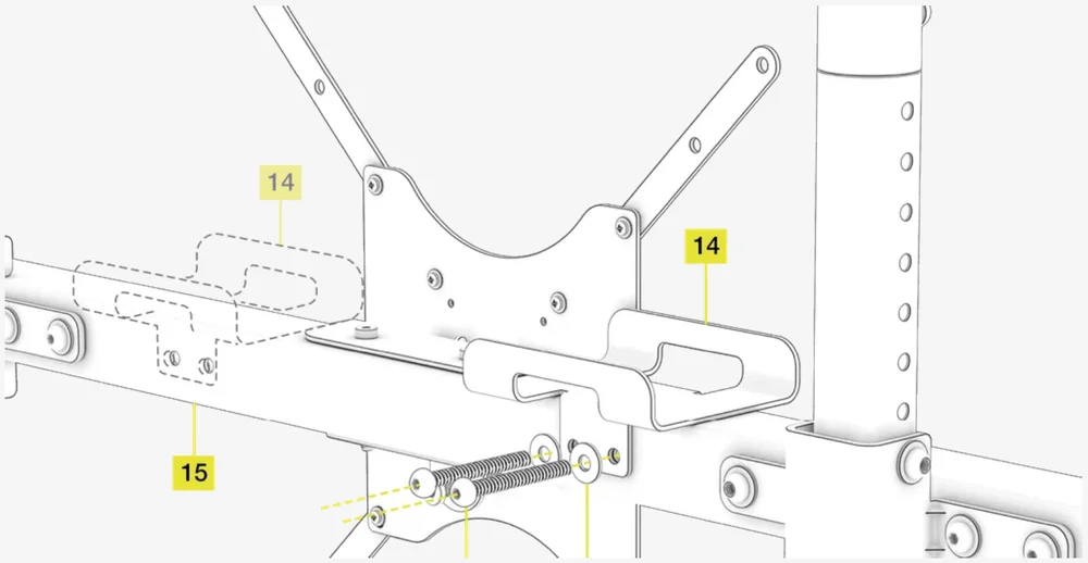
- Position the Power Brick Holder (14) over the corresponding holes in the Main Square Tube Crossmember (6 or 15).
- Secure the holder to the crossmember by screwing in two M8 75mm Bolts (B9) with two M8 Washers (W3).
NOTE: It is possible to mount the included Power Brick Holder (14) on either side of the central VESA mount.
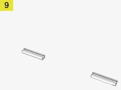
9: Attaching included T-rail mounting bolts
Open the hardware bag labeled T-RAIL MOUNTING BOLTS.
To complete the step, the following hardware and tools will be used:
M4 Allen Key
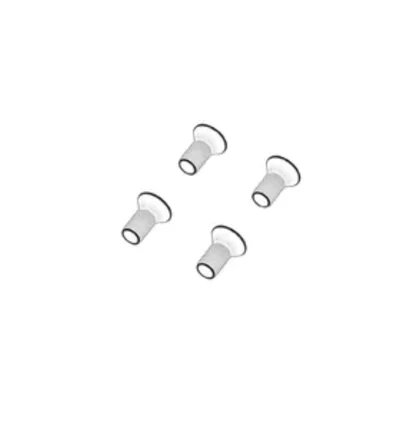
M4 8mm Countersunk Bolts (4x)
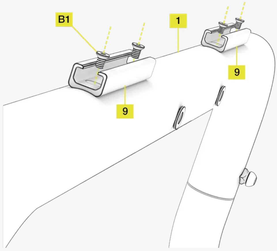
Place the Upper T-Rail Accessory Mounts (9) over the top facing holes on the Top Main Frame Connecting Tube (1) and secure each with two M4 8mm Countersunk Bolts (B1).
NOTE: The T-rail mounts can accept standard T-nuts allowing the mounting of multiple types of Elgato and third party streaming equipment or other accessories.
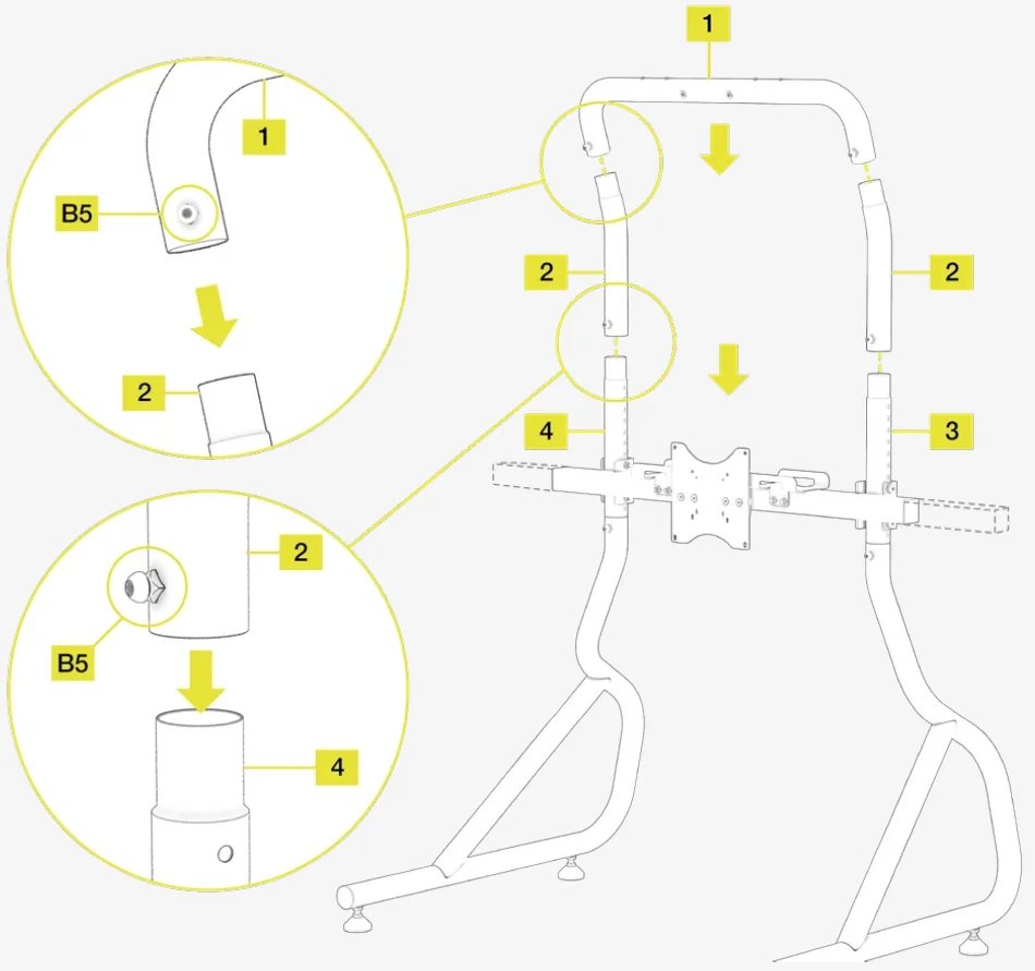
10: Installing an upper monitor mount extension kit (optional)
Open the tool and hardware bags labeled CS MS UPPER MONITOR STEP 1A.
To complete the step, the following hardware and tools will be used:
M8 Allen Key
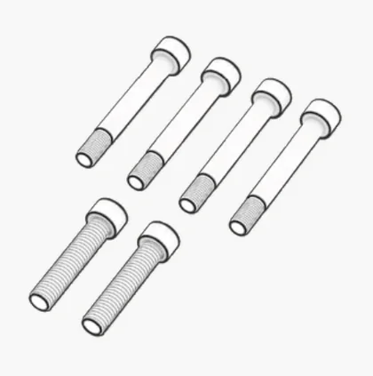
M8 12mm Bolts (4x)
IMPORTANT: Do not overtighten any of the bolts.
- Undo the two M8 12mm Bolts (B5) securing the Top Main Frame Connecting Tube (1) to the Left and Right Side Vertical Adjustment Tubes (4 and 3).
- Separate the Top Main Frame Connecting Tube (1) from the rest of the frame.
3. Connect the Top Main Frame Connecting Tube (1) to the Left and Right Upper Monitor Mount Extension Tubes (2) by sliding them together.
4. Slide the assembled parts onto the Left and Right Side Vertical Adjustment Tubes (4 and 3).
5. Secure all the tubes by screwing in four M8 12mm Bolts (B5).
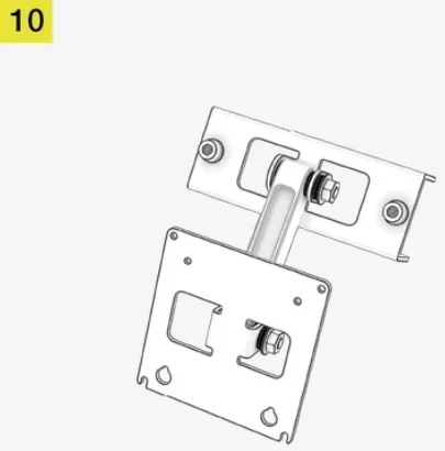
11: Attaching the included upper monitor VESA mounting bracket (optional)
Open the hardware bag labeled CS MS UPPER MONITOR STEP 1B.
To complete the step, the following hardware and tools will be used:
M8 Allen Key
M8 25mm Bolts (2x)
M8 Washers (2x)
- Attach the Upper VESA Mount Bracket (10) to the center of the Top Main Frame Connecting Tube (1) by aligning themounting holes.
- Secure the bracket to the tube by screwing in two M8 25mm Bolts (B7) and two M8 Bashers (W3).
NOTE: The bracket can be installed with the VESA plate facing up or down. In addition, the VESA plate can be rotated around its mounting axis. Ensure the notches on the VESA plate are pointing upwards.
NOTE: The 100mm x 100mm Upper VESA Mount Bracket (10) supports monitors with screens up to 34″ (ultrawide).
TRIPLE SCREEN EXPANSION KIT - INTRODUCTION
Congratulations on purchasing your new Fanatec Triple Screen Expansion Kit. It has been designed and engineered to pair elegantly with your Fanatec ClubSport sim racing cockpit.
Please take a moment to carefully read this guide prior to assembling your Fanatec Triple Screen Expansion Kit.
CAUTION: Your Triple Screen Expansion Kit is engineered from steel for strength and durability.
- Some of the components are heavy. Please exercise proper care when handling them.
- Ensure the chosen build area is clutter free and there is sufficient space for assembly.
- Use a soft floor covering, such as an old blanket or rug, to protect both the finish of your Triple Screen Expansion Kit and floor during assembly.
- To avoid stripping of threads, do not overtighten.
TRIPLE SCREEN EXPANSION KIT - BOX CONTENTS
Triple screen expansion kit - expanded view
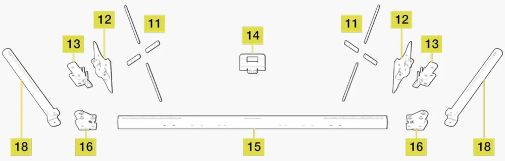
Triple screen expansion kit - box contents
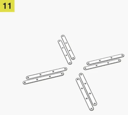
VESA Mount Extension Set (2x)
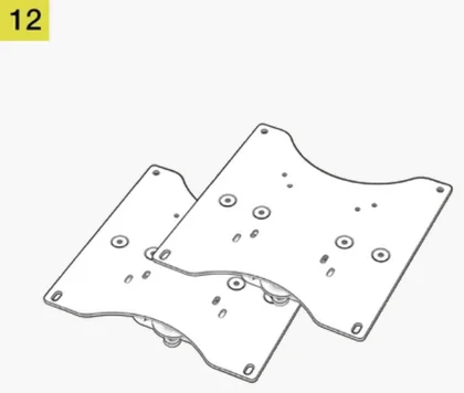
Main VESA Mount Plate (2x)
VESA Mount Fine Adjustment Bracket (2x)
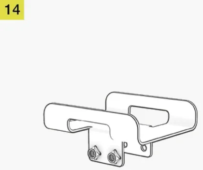
Power Brick Holder
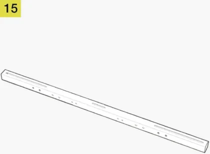
Main Square Tube Crossmember (1450mm)
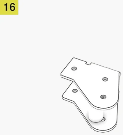
Right Side Angle Bracket
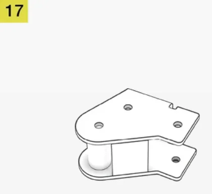
Left Side Angle Bracket
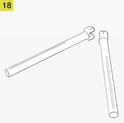
Left and Right Outer Monitor Arms (2x)
Triple screen extension kit - included hardware
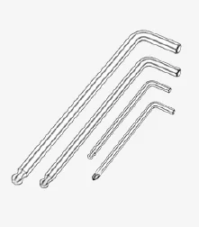
CS MS Tool Kit Bag:
- M4 Allen Key
- M6 Allen Key
- M8 Allen Key
- Phillips Screwdriver
CS MS Velcro Bag:
- Velcro, Black (3x)
CS MS Velcro Bag:
- Velcro, White (3x)
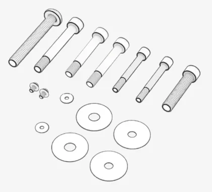
CS MS Spare Parts bag:
- M4 10mm Bolts (2x)
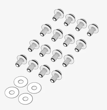
- M4 Washers (2x)
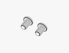
- M6 55mm Shoulder Bolts (2x)
- M8 50mm Bolt (1x)
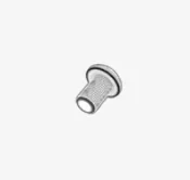
- M8 60mm Shoulder Bolts (2x)
- M8 70mm Shoulder Bolt (1x)
- M8 75mm Bolt (1x)
- M8 Washers (2x)
- M10 Washers (2x)
Power Brick Holder Bolts Bag:
- M8 75mm Bolts (2x)
- M8 Washers (2x)
Triple Mount Step 3 Bag:
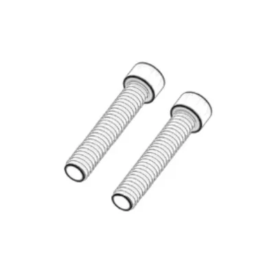
- M8 60mm Shoulder Bolts (4x)
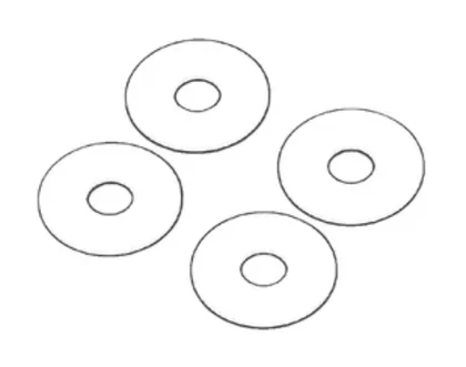
- M10 Washers (4x)
Triple Mount Step 4 Bag:
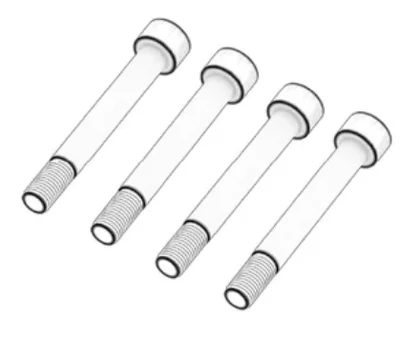
- M8 70mm Shoulder Bolts (2x)
- M10 Washers (2x)
Triple Mount Step 5 Bag:
- M6 55mm Shoulder Bolts (4x)
- M8 50mm Bolts (2x)
VESA Hardware bag:
- M4 12mm Screws (10x)
- M4 15mm Spacer Screws (8x)
- M4 30mm Spacer Screws (8x)
- M4 40mm Spacer Screws (8x)
- M6 12mm Screws (10x)
- M6 16mm Screws (10x)
VESA Extension Mounts Bag:
- M4 12mm Bolts (16x)
- M4 Washers (4x)

TRIPLE SCREEN EXPANSION KIT - ASSEMBLING
IMPORTANT: If you already have the 1450mm crossmember (15) installed, skip steps 1 and 2. If you are upgrading from the Single Monitor Stand to the Triple Screen Expansion Kit, continue with the following steps.
1: Preparing the stand
Open the hardware bag labeled CS MS TOOL KIT.
To complete the step, the following hardware and tools will be used:
M8 Allen Key
- Remove the Power Brick Holder (14).
- Remove the Main VESA Plate (12).
- Remove the VESA Mount Fine Adjustment Bracket (13).
2: Attaching the main square tube crossmember
To complete the step, the following tool will be used:
M8 Allen Key
CAUTION: The replacement Main Tube Crossmember is heavy. Please excersise caution when handling this part.
- Remove the 1000mm Main Square Tube Crossmember (6) and replace it with the 1450mm Main Tube Crossmember (15). Ensure the markings on the crossmember are facing up.
- Secure the crossmember using the same eight M8 25mm Bolts (B7) and eight M8 Washers (W3).
IMPORTANT: Do not overtighten any of the shoulder bolts during steps 3, 4 and 5.
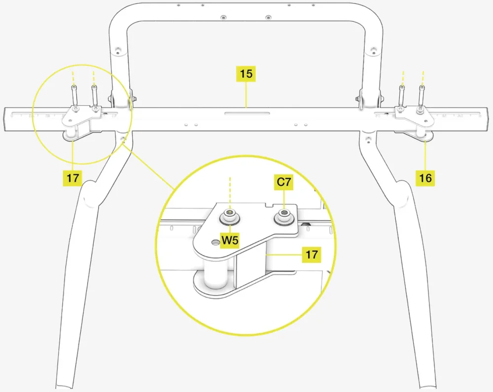
3: Adding the left and right extension arm brackets
Open the hardware bag labeled TRIPLE MOUNT STEP 3.
To complete the step, the following hardware and tools will be used:
M8 Allen Key
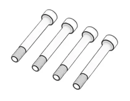
M8 60mm Shoulder Bolts (4x)
M10 Washers (4x)
- Slide the Right Side Angle Bracket (16) over the right side of the Main Tube Crossmember (15) and secure it with two M8 60mm Shoulder Bolts (C7) and two M10 Washers (W5).
- Slide the Left Side Angle Bracket (17) over the left side of the Main Tube Crossmember (15) and secure it with two M8 60mm Shoulder Bolts (C7) and two M10 Washers (W5).
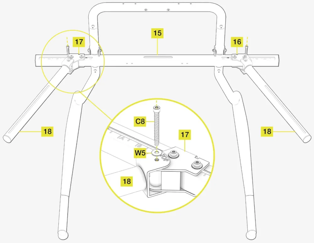
4: Adding the left and right outer arms
Open the hardware bag labeled TRIPLE MOUNT STEP 4.
To complete the step, the following hardware and tools will be used:
M8 Allen Key
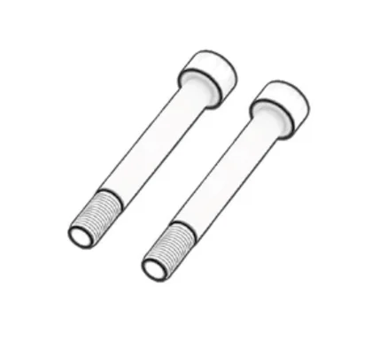
M8 70mm Shoulder Bolts (2x)
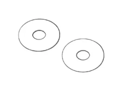
M10 Washers (2x)
- Place the Left Outer Monitor Arm (18) over the Left Side Angle Bracket (17) with the word "TOP" facing up. Secure the arm to the bracket with M8 70mm Shoulder Bolt (C8) and a M10 Washer (W5).
- Place the Right Outer Monitor Arm (18) over the Right Side Angle Bracket (16) with the word "TOP" facing up. Secure the arm to the bracket with M8 70mm Shoulder Bolt (C8) and a M10 Washer (W5).
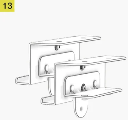
5: Attaching the VESA mount brackets
Open the hardware bag labeled TRIPLE MOUNT STEP 5.
To complete the step, the following hardware and tools will be used:
M8 Allen Key
M6 Allen Key
M8 50mm Bolt (2x)
M6 55mm Shoulder Bolts (4x)
NOTE: If you already have the VESA Mount Fine Adjustment Bracket (13) installed, skip bullet 1.
- Reattach the VESA Mount Fine Adjustment Bracket (13) to the Main Tube Crossmember (15) and secure it using two M6 55mm Shoulder Bolts (C5), removed in STEP 1.
- Attach VESA Mount Fine Adjustment Brackets (13) to the Right and Left Outer Monitor Arms (18).
- Secure both brackets to the arms using two M6 55mm Shoulder Bolts (C5) on each side.
- Screw in M8 50mm Bolt (B8) through the bottom tab of the each VESA bracket (13). See FIGURE A.
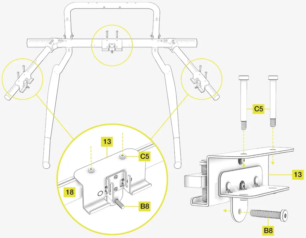
Figure A
5A: Mounting the monitor to the VESA plate
Open the hardware bag labeled VESA HARDWARE.
To complete the step, the following hardware and tools will be used:
M6 Allen Key
M4 Allen Key
M4 12mm Screws (8x)
M6 12mm Screws (8x)
M6 16mm Screws (8x)
M4 15mm Spacer Screws (8x)
M4 30mm Spacer Screws (8x)
M4 40mm Spacer Screws (8x)
NOTE: The included Main VESA mount plates (12) support monitors with up to 200mm x 200mm VESA pattern on their rear panels. If you wish to mount a monitor with larger mount size pattern, please use the VESA Mount Extension Set (11), covered in step 7.
- Determine the size and depth of the VESA mount on the rear panel of your monitor. For recessed VESA mounts, use the appropriate included spacer screws (C2, C3, C4) and screw them into your monitor first.
- Attach the Main VESA Mount Plate (12) to the rear panel of your monitor and secure it by using appropriate bolts (B3, B4).
| VESA Pattern | Bolt size |
|
75mm x 75mm 100mm x 100mm 200mm x 100mm |
M4 12mm (B3) |
|
200mm x 200 mm ... or more |
M6 12mm / 16mm (B4) |
NOTE: The VESA HARDWARE bag includes two spare M4 12mm Bolts, two spare M6 12mm Bolts and two spare M6 16mm Bolts.
6: Adding the main VESA mount plates
NOTE: The VESA mount includes a bezel fine tuning mechanism for aligning multiple bezels with each other. See chapter USING THE BEZEL FINE TUNING ADJUSTMENT MECHANISM in the beginning of this guide for a detailed explanation.
Lower the Main VESA Mount Plates (12) into the slots of all three VESA Mount Fine Adjustment Brackets (13). Ensure the fine tuning bolt heads on the Main VESA Mount Plates (12) are orientated upwards.
7: Attaching the included VESA mount extension sets (optional)
Open the hardware bag labeled VESA EXTENSION MOUNTS.
To complete the step, the following hardware and tools will be used:
Phillips Screwdriver
M4 12mm Bolts (16x)
M4 Washers (4x)
The included VESA Mount Extension Sets (11) are used to mount monitors with VESA mounting pattern larger than 200x200mm.
- Position the VESA Mount Extension Set (11) arms over the corresponding holes of the Main VESA Mount Plate (12).
- Secure the arms by screwing in eight M4 12mm Bolts (B3). Ensure that the bolts are inserted through the backside of the Main VESA Mount Plate (12).
OPTIONAL: As an additional safety measure, you can use the two included M4 Washers (W1) on the two slotted holes on the bottom of the Main VESA Mount Plate (12).
NOTE: Image below shows a standard placement of the extension arms. Depending on your monitor size and VESA pattern, choose a suitable combination of mounting holes. Make sure the VESA mount is securely installed on your monitor before attaching it to the stand.
8: Attaching the included power brick holder accessory (optional)
To attach a single Power Brick Holder, you can use the hardware you uninstalled in step 1. In order to attach two Power Brick Holders, open the additional hardware bag labeled POWER BRICK HOLDER BOLTS.
To complete the step, the following hardware and tools will be used:
M8 Allen Key
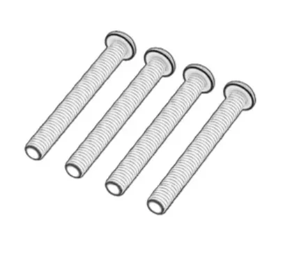
M8 75mm Bolts (2x/4x)
M8 Washers (2x/4x)
- Position the Power Brick Holder (14) over the corresponding holes in the Main Square Tube Crossmember (15) on either side of the VESA mount.
- Secure the holder to the crossmember by screwing in two M8 75mm Bolts (B9) with two M8 Washers (W3).
- To attach the additional Power Brick Holder (14), repeat the process on the other side of the VESA mount.
CARE AND MAINTENANCE
Your Fanatec Single Monitor Stand and Triple Screen Expansion Kit are manufactured to be robust and sturdy during use. However, by following basic care and maintenance steps, you can improve the longevity and performance of your stand.
IMPORTANT: This product is designed for adult use. We recommend adult supervision for any children using this product.
- Routinely (at least once every two weeks) check that all the bolts are sufficiently tightened.
- To protect the finish of the monitor stand, always sufficiently loosen the bolts that secure all adjustable parts when using to prevent scraping or cosmetic damage.
- To clean your monitor stand, use a clean, dry microfiber cloth or a vacuum with a soft bristle attachment.
- Ensure a clutter-free environment before use and check to ensure cables are secure.
- Do not put excessive strain on the outer arms holding the monitors in a triple screen configuration.
WARRANTY
All Fanatec monitor stands have a 2-year warranty.
LEGAL
©2025 CORSAIR MEMORY, Inc. Trademarks belong to their respective owners. All rights reserved. Fanatec is a brand of CORSAIR MEMORY Inc.