マニュアル |クイックスタートガイド
グランツーリスモ® DD Pro

A - パッケージ内容

A- グランツーリスモ® DD Pro ×1

B- 1x グランツーリスモ® DD Pro 用ステアリングホイール + 1x QR2 Lite ホイールサイド

C- 1x CSLペダル

D- 1x CSL DDテーブルクランプ

E- 4個 M6x8 mm Tナット

F- 1x 電源装置

G- 電源コード(地域別)×1

H- USB Type-A 対 Type-C ケーブル 1本

I- RJ12ケーブル 1本

J- 1x T20 トルクスレンチ
B - セットアップを計画する
GT DD PROの使用を開始するには、まずホイールベースとペダルをハードマウントするか、CSL DDテーブルクランプを使用するかを選択します。クイックリリースシステムでステアリングホイールを接続し、付属のUSBケーブルを使用してGT DD PROをPlayStation®5コンソールまたはPlayStation®4コンソールに接続してください。効果的な組み立てとセットアップ手順のためには、本マニュアルの章順に従うことが重要です。
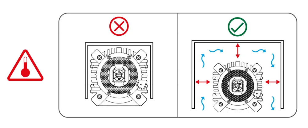
注意:GT DD PRO背面ポートへの周辺機器の接続方法については、G章「接続」を参照してください。すべての機器は電源投入前にGT DD PROに接続し、正常な検出と動作を可能にしてください。損傷を防ぐため、必ず同梱のUSBケーブルを使用してください!ホイールベース周囲に十分な空間を確保し、空気の循環を可能にしてください。自然換気で十分です。
C - テーブルクランプアタッチメント

ステップ1 -ホイールベースをテーブルなどの高い平らな面に逆さまに置きます。
注:ホイールベースに傷がつかないよう、表面に柔らかい乾いたタオルまたは布を敷いてください。

ステップ2 -部品d.2を部品dの中央に挿入します。部品d.2を所定の位置に保持しながら、部品dをホイールベースの底部Tスロットレールにスライドさせて取り付けます。
注意:指を挟まないようご注意ください。

ステップ3 -部品d.3を部品d.3に挿入します。部品d.2にねじ込み、しっかりと固定されるまで締め付けます。

ステップ4 -組み立てた部品を両手でそっと持ち上げ、慎重に直立させます。

ステップ5 -組み立てたクランプを、天板の厚さが5mmから60mmの机/テーブルの端に置き、部品d.4を使用してクランプ機構をしっかりと固定します。
注意:机/テーブルの端がクランプストッパーに接触していること、およびクランプパッドが平らになっていることを確認してください。
D - ハードマウント

ホイールベースの底部(左)または側面(右)からのハードマウントは、部品E(Tナット)を使用して可能です。

ホイールベースの底部(左)または側面(右)からのハードマウントは、部品E(Tナット)を使用して可能です。
注意:ホイールベース前部の取り付け穴はハードマウント用ではありません!静的シフターパドルやダッシュディスプレイなどの周辺機器取り付け専用です。ねじ山長:10mm
注:ボルトは付属しません。ハードマウント時は高品質ボルトのみ使用してください。ボルト仕様:M6x(10+X) mm
E - ステアリングホイール取付金具

ステアリングホイールを取り付けるには、ステアリングホイールQR2アダプターをホイールベースQR2アダプターにしっかりと押し付けてください。

ステアリングホイールを取り外すには、ステアリングホイールQR2アダプタースリーブを引っ張りながら、同時にステアリングホイールをホイールベースから引き離します。
F - ペダル設定

硬質床面またはカーペット面での使用に適し、固定式設置は不要です。

上記の寸法および測定データに基づき、ペダルセットアップのハードマウントを計画してください。


注意:かかと受け穴をハードマウントする際は、部品c.2を使用してください。
G - 接続

互換ハードウェア
PlayStation公式ライセンス製品ではないFanatec製ステアリングリム/ハブとの互換性については、ソニー・インタラクティブエンタテインメントによるテストおよび推奨は行っておりません。
H - オン / オフ

ホイールベースの電源を入れるには、システムを電源に接続し、ホイールベース右側の電源ボタンを約1秒間押してください。その後、ホイールベースは直ちに起動時キャリブレーションを実行します。

ホイールベースをオフにするには、電源ボタンを3秒間長押ししてください。
I - モード

モードを切り替えるには、ホイールベースの電源が入っている状態で、電源ボタンまたはハイライト表示されたボタン組み合わせを短く押してください。電源ボタンを照らすLEDの色が現在のモードを示します。

BLUEPlayStation® - PS5用TM コンソールとPS4TM コンソール。
PURPLEPS4TM 互換性 - CSL Elite Wheel Base + PS4 として検出されましたTMPS5用TM コンソールとPS4TM GT DD PROがゲームで検出されない、またはサポートされていない場合のコンソール。
REDPC - PCでの使用およびファームウェア更新用。
YELLOWPC互換性 - ClubSport Wheel Base V2.5として検出されます。GT DD PROがゲームで検出されない、またはサポートされていない場合のPC用。
J - ファームウェア更新

PCドライバーをインストールした後、ホイールベースをUSB経由でWindows PCに接続してください。ホイールベースがPCモードになっていることを確認してください(手順については第I章「モード」を参照)。PCドライバーを開き、「ファームウェア更新」を選択し、「ファームウェアマネージャーを開く」を選択すると、更新プロセスが案内されます。
K - センターキャリブレーション

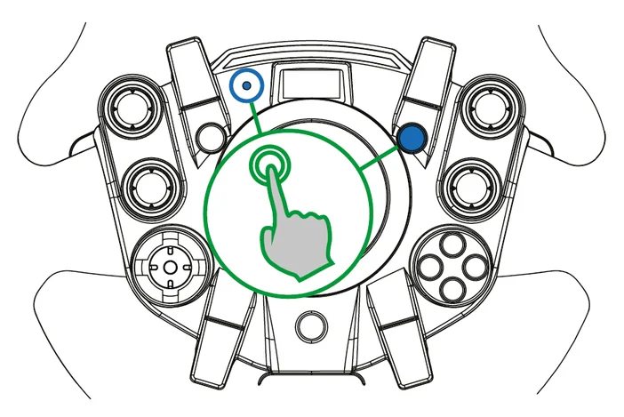
センター位置を手動で調整する必要がある場合があります。右図のようにステアリングホイールの表示部に「CAL」が点滅表示されたら、以下の手順に従ってください。

ステップ1- チューニングメニューに入ります。

ステップ2- ステアリングホイールを中央に合わせる。

ステップ3- ボタンを組み合わせて押す。
ステップ4- チューニングメニューを終了します。
L - シフターキャリブレーション
ステアリングホイールには、シフターキャリブレーションを実行するための特定のボタン操作が設定されています。シフターキャリブレーションはPCドライバーでも実行可能です。ファームウェア更新後、キャリブレーションされていないHパターンシフターが接続され検出されると、ホイールベースは自動的にシフターキャリブレーションを要求します。メニューが以下の手順に従ってキャリブレーションを案内します。
ステップ1- Hパターンシフターのキャリブレーションモードに入るには、ボタンを組み合わせて押してください。

ステアリングホイールのOLEDディスプレイに指示が順に表示されます。

ステップ2- H字型シフトレバーをステアリングホイールディスプレイに表示された位置に入れ、各ギア位置で指示されたボタンを押して操作を確認してください。
M - チューニングメニュー
ナビゲーション
ステップ1- チューニングメニューに入ります。

ステップ2- Dパッドを使用してチューニングメニューのパラメータを操作します。
ステップ3- チューニングメニューを終了します。
チューニングメニュープロファイル
注記:接続したFanatecステアリングホイールのクイックガイドを参照し、ボタン操作によるセンターキャリブレーションなど各種機能を行ってください。調整パラメータは変更される可能性があり、将来のファームウェアバージョンで変更される場合があります。
標準チューニングメニュー
1つの自動設定 + 1つのカスタム設定 - コアパラメータのみ
詳細チューニングメニュー
1つの自動設定 + 5つのカスタム設定 - 全パラメータ
自動設定
自動設定により、ゲームは開発者が意図した通りのフォースフィードバック体験を実現するため、チューニングパラメータ値を制御できます。ユーザーによるチューニングパラメータ値の手動変更はできません。
チューニングメニューボタンを押してチューニングメニューに入り、「A SET」を選択して自動設定を有効にします。ゲームが自動設定をアクティブに使用している場合、「A.SET.」が表示されます。自動設定を使用しているゲームがない場合、工場出荷時のデフォルトチューニング設定が使用されます。
自動調整されるチューニングパラメータを確認するには、チューニングメニューボタンを押してチューニングメニューに入ります。「A SET」を選択し、目的のチューニングパラメータに移動します。そのパラメータを変更しようとすると、自動調整値が表示されます。
標準チューニングメニュー
チューニングメニューボタンを押して初めてチューニングメニューに入ると、このチューニングメニューがデフォルトで有効になります。「A SET」は自動設定プロファイルを示し、「C SET」はカスタム設定プロファイルを示します。
この設定プロファイルでは、以下のアクセスが可能です:
- SEN(感度)
- FF(フォースフィードバック)
- NDP(ナチュラルダンパー)
- BRF(ブレーキ力)
BRFは、ロードセルブレーキを搭載したペダルセットが接続されている場合にのみ利用可能です。これらのチューニングパラメータは、可能な限り最適な標準チューニング体験を確保するため、範囲がわずかに調整されています。
サイクル標準および高度な調整メニュー
ステアリングホイール上のチューニングメニューボタンを4秒間長押しすると、下図のように標準チューニングメニューと詳細チューニングメニューを切り替えられます。さらに6秒間長押しすると、カスタム設定プロファイルがデフォルト値にリセットされます。チューニングメニューをリセットすると、標準チューニングメニューが有効になります。
チューニングメニューボタンを4秒間押し続けると、メニューが変更されます。
チューニングメニューボタンを6秒間押し続けると、リセットが実行されます。
詳細設定メニュー
「A SET」は自動設定プロファイルを示し、「1 SET」から「5 SET」はカスタム設定プロファイルを示します。これらのプロファイルでは、すべてのチューニングパラメータに制限なく完全にアクセスできます。
チューニングメニューのパラメータ
SEN(感度)
標準SEN範囲: 180 … 1080 - AUTO SENデフォルト: AUTO
高度なSEN範囲: 90 … 2520 - AUTO SENデフォルト: AUTO
感度(SEN)は回転角度を定義します。SENが90に設定されている場合、ステアリングホイールは90°(キャリブレーション済み中心位置から左右各45°)のみ回転可能です。SENを2520に設定すると、ステアリングホイールは2520°回転可能(キャリブレーション済み中心位置から左右各1260°)。SENをAUTOに設定すると、感度はPCドライバーまたはゲーム本体(対応機能がある場合)によって制御される。
FF(フォースフィードバック)
標準FF範囲: 005 … 100 - FFデフォルト: 100
高度FF範囲: OFF 001 … 100 - FFデフォルト: 100
フォースフィードバックは、ソフトウェア/ゲームからのフォースフィードバック効果がホイールベースに送信される際のモーターの最大出力を定義します。FFがOFFに設定されている場合、ホイールベースモーターによるフォースフィードバック効果は一切実行されません。FFが001に設定されている場合、モーターは最大出力の1%のみを実行します。FFが100に設定されている場合、モーターは最大出力の100%を実行します。最終的なトルク出力は、フォースフィードバック修正値(下記参照)やゲーム内設定など、複数の要因によって影響を受けます。より強いフィードバックを得るには、ゲーム内の強度値を上げるよりも(クリッピングを避けるため)、チューニングメニューでより高い「FF」値を設定することをお勧めします。
FFS(フォースフィードバックスケーリング)
FFS範囲: LIN (リニア) / PEA (ピーク) - FFSデフォルト: PEA
FFスケーリングは、ピーク力と保持力の間で一貫した出力を保証し、ゲーム出力とトルク出力の一般的な直線性を向上させるため、最大FFB出力をわずかに低減します。LINはこの設定を有効にし、PEAはこの設定を無効にします。
| PSU | FFS 範囲 | 最大トルク |
| 標準電源ユニット | LIN | 4 ニュートンメートル |
| PEA | 5 ニュートンメートル | |
| ブーストキット 180 PSU | LIN | 6 ニュートンメートル |
| PEA | 8 ニュートンメートル |
NDP(ナチュラルダンパー)
標準NDP範囲: 25 … 100 - NDPデフォルト: 50
高度なNDP範囲: OFF 01 … 100 - NDPデフォルト: 50
ナチュラルダンパーは追加の減衰効果を提供し、OFFから100まで調整可能です。100では最も強い減衰効果が得られ、ステアリングの加速度と角度に反応します。OFFにすると追加の減衰効果がなくなり、ステアリングホイールを回しやすくなります。ナチュラルダンパーはオーバーステア時のホイール速度制御に有用であり、ホイール振動の低減にも寄与します。振動は主にフィードバックループの遅延によって発生し、高トルクモーター向けに最適化されていないレーシングゲームで顕著に現れます。デフォルト値の50は、ステアリング応答性と振動抑制のバランスを提供します。
NFR(自然摩擦)
NFR範囲: OFF 001 … 100 - NFRデフォルト: OFF
ナチュラルフリクションは、ステアリング部品の機械的な感触をシミュレートするために使用されます。設定値を高くすると、ステアリングホイールを回転させる際の抵抗が増加します。これにより、パワーステアリングのない車両や、非常に幅の広いタイヤを装着した車両の運転感覚を向上させることができます。また、この設定は振動の防止にも役立つ場合があります。
NIN(ナチュラル・イナーシャ)
NIN範囲: OFF 001 … 100 - NINデフォルト: OFF
ナチュラル・イナーシャは追加のステアリング重量をシミュレートします。これは特に、当社のCSL Elite / CSLシリーズなどの軽量ステアリングホイールを使用する際に有用です。さらに、方向転換時のナチュラル・フリクション設定は滑らかになります。
INT (FFB補間)
INT範囲: OFF 01 … 20 - INTデフォルト: 11
FFB補間は、FFBの詳細を損なわずにゲーム出力をフィルタリングすることでFFBを滑らかに補間します。OFF = フィルタなし、01 = 最低フィルター、20 = 最高フィルター。
FEI(力効果強度)
FEI範囲: 000 ... 100 - FEIデフォルト: 100
フォース効果強度:フォース効果の全体的な強度と滑らかさを調整します。000が最も滑らかです。100が最も鋭く直接的な効果です。このパラメータを調整することで、一部のゲームにおける荒い、またはスパイク状のフォースフィードバック信号を改善できます。
力/ばね/ダンパー効果
FOR 範囲: OFF 010 … 120 - FOR デフォルト: 100
SPR 範囲: OFF 010 … 120 - SPR デフォルト: 100
DPR 範囲: OFF 010 … 120 - DPR デフォルト: 100
これらのFFBモディファイアを使用すると、ゲームのFFB信号を変更できます(ゲームがこれらの効果をサポートしている場合のみ適用可能)。理論上、ゲームが送信できる信号タイプは3種類あります。フォース(ステアリングホイールを特定方向に強制的に動かす)。スプリング(ステアリングホイールを動的中心点へ引き戻す)。ダンパー(摩擦を生成する)。
注:すべてのゲームが3種類の効果をすべて使用しているわけではなく、一部のゲームでは1種類のみを使用して3つの効果すべてを表現している。
重要:スプリングを低い値またはOFFに設定した場合、センターキャリブレーション実施後、ホイールベースは接続されたステアリングホイールを正しいセンター位置に戻せなくなります。FFB効果が弱く、他のゲームと比較して弱い場合にのみ、これらの値を100%以上に調整してください。これらの値のいずれかまたは複数を上げることで、モーターへの負荷が増加し、発熱が増加する可能性があります。
BLI(ブレーキレベルインジケーター)
BLI範囲: 001 … 100 - OFFBLIデフォルト: OFF
001から100までの値でブレーキペダル振動の作動点を設定します(ClubSport Pedals V3 / V3i接続時のみ有効)。この機能は独立して動作するため、あらゆるゲームで使用可能です。しきい値ブレーキ技術の習得に有用です。OFFにすると、ペダル振動はゲーム側で直接制御されます(対応している場合)。
SHO(衝撃/振動強度)
SHO範囲: OFF / ON - SHOデフォルト: ON
Fanatecステアリングホイールおよびペダルセットに搭載された振動モーターによる衝撃/振動の強度は、OFFまたはONに設定可能です。対応ゲームでは、これらの振動モーターを直接使用できます。
MPS(マルチポジションスイッチ機能)
MPS: AUTO; ENC; CONST; PULSE - MPSデフォルト: AUTO
ENC(エンコーダー):MPSは2つのボタンをシミュレートします。MPSを左に回転させたときと、右に回転させたときにそれぞれ対応します。
PULSE(パルス):MPSは各位置に対して特定のボタン信号を出力します。スイッチを回転させた際に単一のパルスとして送信されます。
CONST(定数):MPSは各位置に対して定常的なボタン信号を出力します。
AUTO(ゲーム依存):ゲームが適切なモードを決定します。
注記:付属のステアリングホイールではサポートされていません。Fanatec製マルチポジションスイッチ搭載ステアリングホイール(例:ClubSport Steering Wheel Formula V2.5)を使用している場合にのみ利用可能です。さらに、この機能が動作するにはゲーム側でサポートされている必要があります。
AP(アナログパドル)
AP: CbP; CH; bt; AnA - APデフォルト: CbP
CbP(クラッチバイトポイント):この機能はアナログクラッチ軸を備えたあらゆるゲームで使用可能です。左右のアナログパドルは並行して動作し、どちらのパドルをより強く押したかによって主パドルが決定されます。
CH (クラッチ / ハンドブレーキ):左パドル = クラッチ。右パドル = ハンドブレーキ。
BT (ブレーキ / スロットル):左パドル = ブレーキ。右パドル = スロットル。
AnA (マッピング可能な軸):パドルは2つの追加軸としてマッピング可能。一部のステアリングホイールではアナログジョイスティックと共有される場合があります。
注記:付属のステアリングホイールではサポートされていません。アナログパドルモードの切り替え専用ハードウェアスイッチを持たないアナログパドルを備えたFanatec製ステアリングホイールまたはアドオンシフターパドルを使用している場合のみ利用可能です。
| クラッチの咬み始め位置設定手順 | |
| 簡略化 | 上級 |
|
• クラッチパドルを両方同時に少なくとも5%まで押して作動させ、 • 片方のペダルを離し、もう片方は完全に踏み込んだままにします。表示 • リリースしたパドルを、車両のクラッチ • バーチャルスタートライトが緑に変わったら、完全に踏み込んだパドルのうち片方の • |
• クラッチレバーを完全に押し続けてください。 • ファンキースイッチを押すTM Dパッドスティックを下に押す。ディスプレイに「100」が表示される • パドルを離すと設定値が確定・保存されます。各チューニングメニュースロット(S_1 ... S_5)ごとに個別に保存された値( • レース開始時、両方のパドルを再度押すとバイトポイントモードが作動します。 • |
BRF(ブレーキ力)
CSP V3 / V3i: Lo -> 001 ... 100 -> Hi - BRFデフォルト: 050
CSL E P LCK / CSL P LCK: Lo -> 010 ... 100 -> Hi - BRFデフォルト: 050
ブレーキフォースは、ロードセル式ブレーキペダルにおいて100%のブレーキ入力に達するために必要な力を変更する機能です。ロードセル式ブレーキを備えたペダルセットがRJ12経由でホイールベースに接続され、USB経由でPCに接続されている場合に利用可能です。「Lo」は最小のブレーキ圧力を要求し、「100」は最大のブレーキ圧力を要求します。
注記:付属のCSLペダルではサポートされていません。
N - 清掃
乾いた、またはわずかに湿らせたマイクロファイバークロスでのみ清掃してください。
注意:洗浄液の使用は、ホイールベース、ステアリングホイール、ペダルを損傷する恐れがあります。
O - トラブルシューティング
GT DD PROは、本マニュアルに明示的に記載されている方法以外で改造してはなりません。Corsair Memory, Inc.は、本デバイスに含まれる電子機器、ハードウェア、ソフトウェア、およびファームウェアの解析および利用を明示的に禁止します。GT DD PROの使用に関して問題が発生した場合は、以下のトラブルシューティングガイドをご利用ください。詳細情報および連絡先はhelp.fanatec.comでご確認いただけます。
GT DD PROが正常に動作しない場合:
| 問題の説明 | 解決策 |
| GT DD PROのファームウェア更新後、ステアリングホイールが正しく中央位置に設定されません。 | GT DD PROのファームウェア更新後、ホイール中心位置を手動でキャリブレーションする必要があります。詳細は本マニュアルのJ「センターキャリブレーション」を参照してください。 |
| GT DD PROのファームウェア更新後、Hパターンのシフトレバーが正常に動作しません。 | GT DD PROのファームウェア更新後、Hパターンシフターは手動でキャリブレーションする必要があります。詳細は本マニュアルのK「シフターキャリブレーション」を参照してください。 |
| 運転席の窓には、取り付けられたステアリングホイールが表示されません。 | GT DD PROを最新のファームウェアバージョンに更新していることを確認してください。このファームウェアは最新のPCドライバーに含まれており、https://www.fanatec.com/s/download-apps-driver からダウンロードできます。 |
| ステアリングホイールのクイックリリース内部のピンを確認してください。これらは曲がったり損傷したりしてはいけません。 | |
| 別のステアリングホイールをお試しください。それでも検出されない場合、GT DD PROが故障している可能性があります。 | |
| PCドライバーはホイールベースを更新モードに切り替えることができません。 | 電源がOFFの状態で、電源ボタンを8秒間長押しするとブートローダーモードで起動します。ファームウェア更新アシスタントを使用してファームウェアの更新を試みてください。 |
| チューニング表示が何も表示されない、または正常に動作していません。 | 別のステアリングホイールをお試しください。それでも正常に動作しない場合は、GT DD PROが損傷している可能性があります。 |
| ステアリングホイールのクイックリリース内部のピンを確認してください。これらは曲がったり損傷したりしてはいけません。 | |
| GT DD PROで起動後、起動時のキャリブレーションが正常に動作しません。 | GT DD PROを最新のファームウェアバージョンに更新していることを確認してください。ファームウェアはhttps://www.fanatec.com/s/download-apps-driverからダウンロードできます。 |
| GT DD PROの起動時キャリブレーション後、接続されたステアリングホイールが正しいセンター位置に戻らない。 | ホイールベースは手動でのセンターキャリブレーションが必要となる場合があります。詳細は本マニュアルのJ章「センターキャリブレーション」を参照してください。 |
| 特定のゲームにおいて、RevLED、FlagLED、および/またはディスプレイが動作しません。 | 古いタイトルでは最新のホイールベースに対応していない場合があります。解決策として「PC互換モード」(黄色LED)への切り替えが有効です。また、一部のタイトルや機能のサポートを追加する可能性があるFanatecアプリもご確認ください。 |
| Fanatecのカスタマーサポートに連絡するにはどうすればよいですか? | 当社ウェブサイトにはチャットサービスがございます。または、Fanatecアカウントの「マイプロダクト」セクションからサポートチケットを作成いただけます。https://help.fanatec.com/hc/en-us |
| PCドライバーまたはホイールベースがCSLペダルを認識しません。 | ホイールベースおよびClubSport USBアダプターのファームウェアを、最新のPCドライバーに含まれる最新バージョンに更新してください。PCドライバーはhttps://www.fanatec.com/s/download-apps-driverからダウンロードできます。 |
| 使用されるRJ12ケーブルは、CSLペダルパッケージ内容物に含まれるもののみであることを確認してください。 | |
| RJ12ケーブルが、ガスペダルモジュール上のCSLペダル、およびホイールベースとClubSport USBアダプターの正しいポートに接続されていることを確認してください。 | |
| 起動後、PCドライバによってCSLペダルのペダル信号が正しく表示または確認されません。 | CSLペダルを起動する際には、各ペダルレバーを最初に最大位置まで押し込み、その後完全に最小位置まで戻す必要があります。 |
P - ビデオガイド