HANDBUCH | KURZANLEITUNG
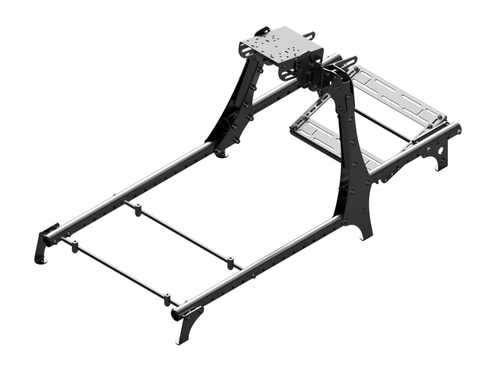
CSL-Cockpit
Die englische Version ist hier verfügbar - English
Bei weiteren Problemen wenden Sie sich bitte an Kundenbetreuung
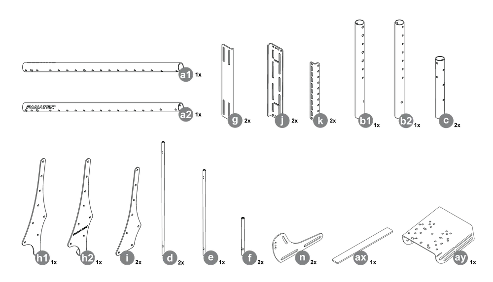
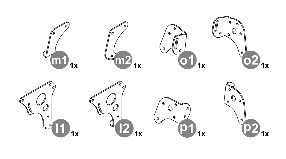
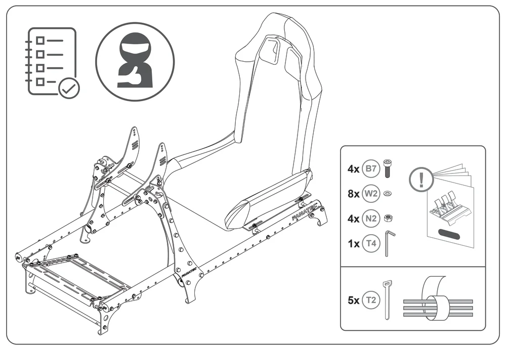
PAKETINHALT

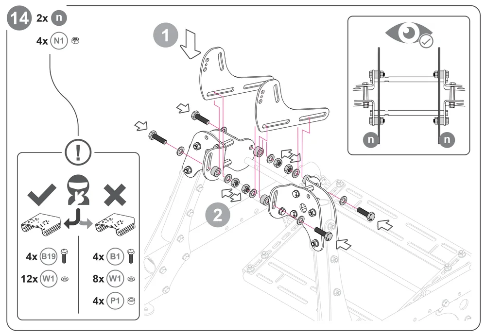
B1 – 4x – M10 x 35 mm
B2 – 20x – M8 x 60 mm
B3 – 8x – M8 x 20 mm
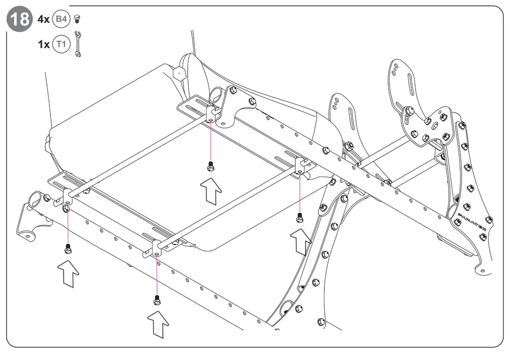
B4 – 46x – M8 x 14 mm
B6 – 4x – M6 x 16 mm
B7 – 4x – M8 x 25 mm
W1 – 24x – M10 Unterlegscheibe
W2 – 110x – M8-Unterlegscheibe
W3 – 4x – M6 Unterlegscheibe
W4 – 4x – M8 Unterlegscheibe
N1 – 4x – M10-Mutter
N2 – 32x – M8-Mutter
P1 – 4x – M10 Distanzstück
P2 - M8 Zylindermutter
P3 – M8-Stange
P4 – 4x – M8 Sechskantmutter (lang)
P5 – 4x – M8 Sechskantmutter (kurz)
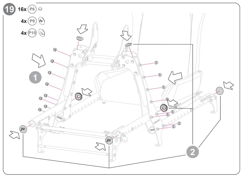
P6 – 16x – 13 mm Kappen
P7 – 6x – Gummipads
P8 – 6x – Filzunterlagen
P9 – 4x – Rohrkappen
P10 – 4x – Kabelkappen
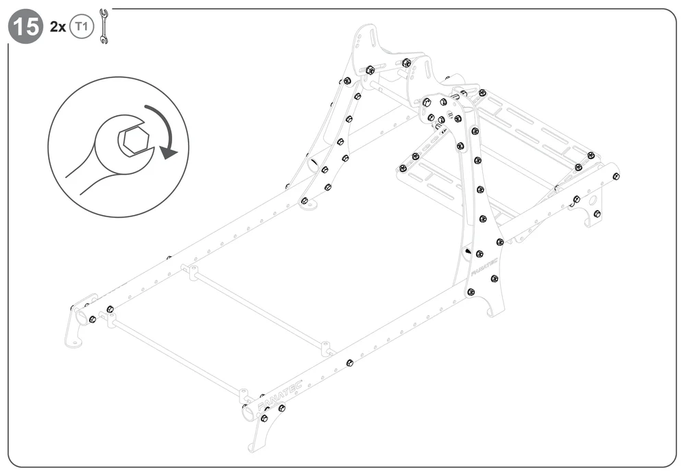
T1 – 2x – 13 mm / 16 mm
T3 – 1x – 5 mm
B11 – 4x – M8 x 14 mm
T2 – 5x – Klettband
T4 – 1x – 6 mm
W7 – 4x – M8 3 mm Unterlegscheibe
B19 – 8x – M10 x 25 mm
HINWEIS: Sitz separat erhältlich!

B12 – 4x – M8 x 20 mm
ERSTE SCHRITTE


Optional
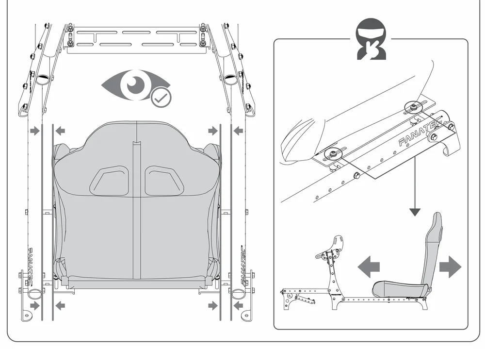
COCKPIT-BAUGRUPPE


HINWEIS: Bevor Sie fortfahren, lesen Sie bitte die Anleitung für die CSL Cockpit-Monitorhalterung, wenn Sie das Cockpit mit einer Monitorhalterung zusammenbauen.


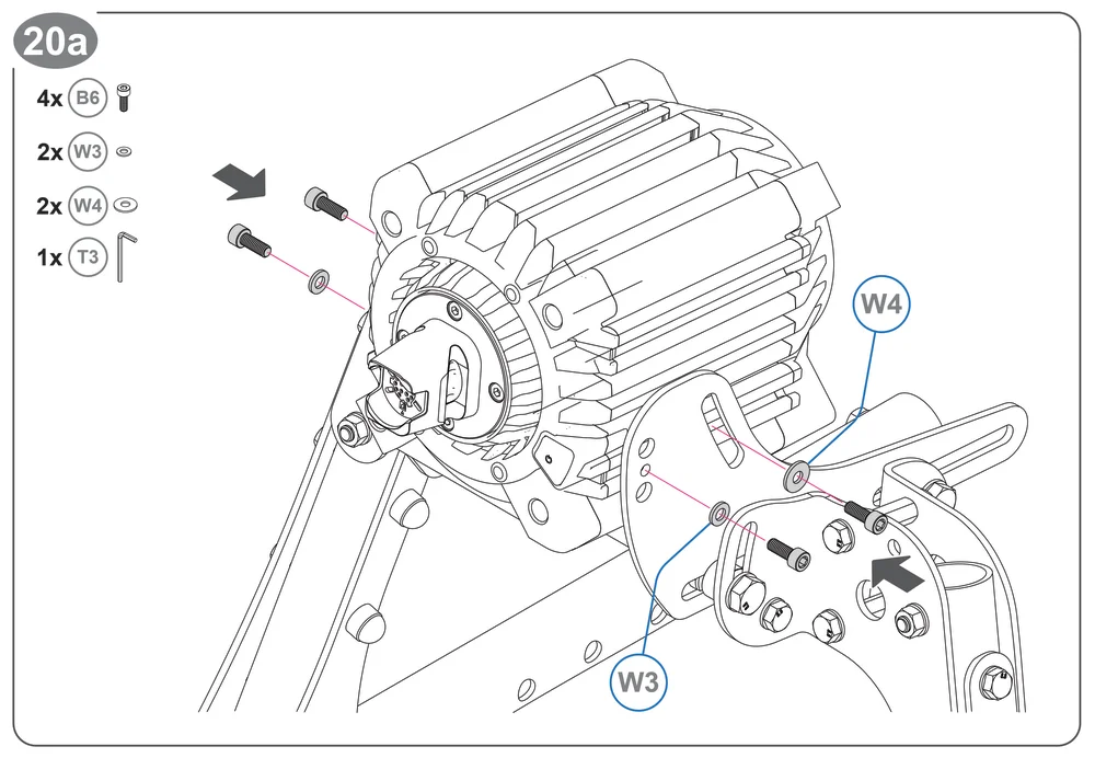
Fahren Sie je nach Ihrem Radstand mit Schritt 20a, 20b oder 20c fort.
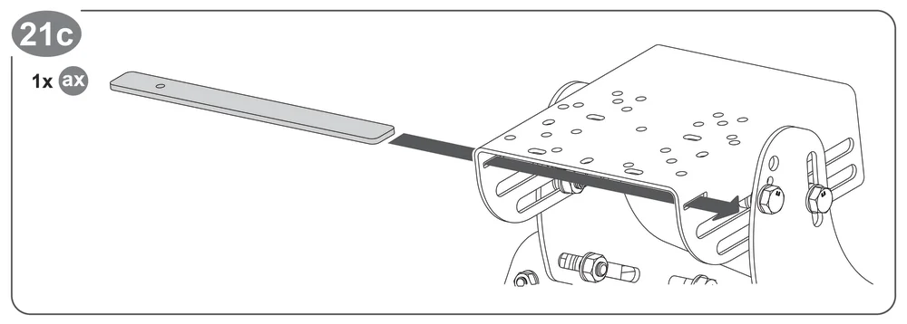
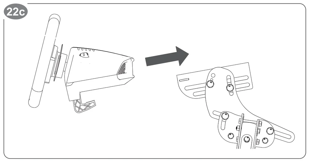
HINWEIS: Die Schritte 20c bis 23c gelten speziell für Besitzer von G29 / 920 / 923.
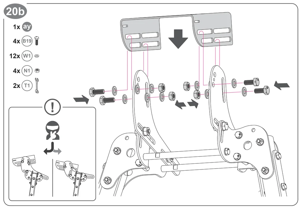
HINWEIS: Positionieren Sie das Teil„ay“ im gewünschten Winkel.
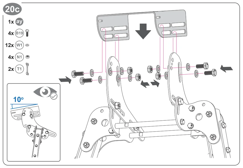
HINWEIS: Die Positionierung des Teils„ay“ in einem Winkel von 10 Grad nach unten ist für den G29 / 920 / 923 optimal.
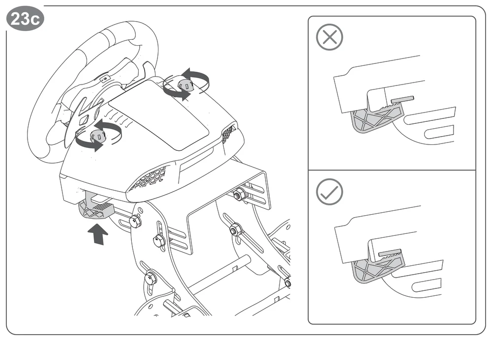
Es sind keine zusätzlichen Schrauben erforderlich, um den G29 / 920 / 923 weiter zu sichern.
Fanatec.com/Handbücher
UNTERSTÜTZUNG
APP: https://www.fanatec.com/eu/en/s/download-apps-driver
Häufig gestellte Fragen: https://help.fanatec.com/hc/
Die Produktgarantie wird von Corsair Memory, Inc. gewährt. Beachten Sie das beiliegende Garantieblatt sowie die Allgemeinen Geschäftsbedingungen von Corsair Memory, Inc. unter www.fanatec.com.