MANUAL | QUICK START GUIDE
Podium Button Module Endurance
PACKAGE CONTENTS
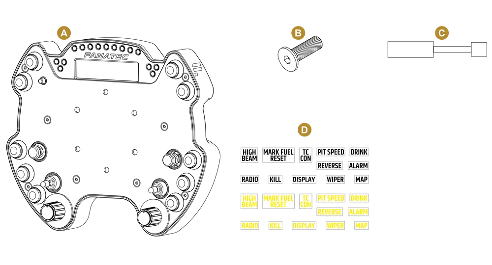
A - 1x Podium Button Module Endurance
B - 6x M5x25mm countersunk bolts
C - 1x DataPort-C to RJ12 adapter
D - 1x Endurance style sticker set
NOTE: Please download our latest Wheel Base firmware from https://fanatec.com/driver
INTELLIGENT TELEMETRY MODE (ITM)
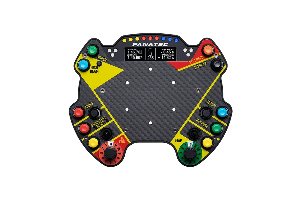
A small “ITM” icon in the bottom right of the BME display shows if ITM is accessible. To scroll through the screens, press and hold the Tuning Button while rotating the FunkySwitch™ left or right.
To access ITM on the Podium Base display, press and hold the Tuning Button while pressing UP with the FunkySwitch™, which will show the legacy screen and a small “ITM” icon in the bottom right if ITM is accessible. Scroll through screens by keeping the Tuning Button held down while pressing left or right with the FunkySwitch™.
NOTE: ITM functions require the use of FanaLab on a Windows PC.

1 - Tuning Button
2 - FunkySwitch™
CENTER CALIBRATION
If a center calibration is needed (e.g. after firmware update of the wheel base) when using the button module you need to press the tuning button as highlighted on the picture below to enter the Tuning Menu.
When Tuning Menu is active press the analogue stick and the FunkySwitchTM simultaneously to calibrate the wheel center.

1 - Tuning Button
SHIFTER CALIBRATION
To enter shifter calibration mode, simultaneously press the Tuning Button and the button highlighted below.

1 - Tuning Button
TUNING OPTIONS
To enter the Tuning Menu, press the Tuning Button. To navigate inside the menu, use the FunkySwitch™. Press it up or down to access the five setups. Press the FunkySwitch™ right or left to go through the options and rotate the FunkySwitch™ to change option values.

1 - Tuning Button
2 - FunkySwitch™
WHEEL BASE MODES
To switch between wheel base modes, simultaneously press and hold the two buttons highlighted below, for one second.

ATTACHING THE BUTTON MODULE ENDURANCE TO THE PODIUM HUB

• Align the Podium Button Module Endurance with the mounting holes of the Podium Hub.
• Place a suitable wheel rim (e.g. UH R300, UH R911, UH R911S) on top of the Podium Button Module Endurance.
• Use the longer mounting bolts (B) that are included in the Podium Button Module Endurance package and tighten down the Wheel Rim.
• Connect the DataPort-C cable of the Podium Button Module Endurance to the connector on the bottom of the Podium Hub.

NOTE: The Podium Button Module Endurance is only suitable for steering wheels with a 6x70mm hole pattern.
ATTACHING THE BUTTON MODULE ENDURANCE TO THE CLUBSPORT UNIVERSAL HUB FOR XBOX ONE

- All regular button clusters and Universal Hub FunkySwitch™ must be removed before installing the Podium Button Module Endurance.
- Loosen the four bolts on the backside of the Universal Hub.
- Open the front cover and connect the RJ12 to DataPort-C adapter to the RJ12 connector.
ATTENTION: Be careful to position cable in one of the cable holes of the Universal Hub to avoid pinching the cable.

- Close the front cover and tighten the bolts.

NOTE: To use the Podium Button Module Endurance with shifter paddles, they must be attached to the rearward set of mounting holes.
- Align the Podium Button Module Endurance with the mounting holes of the Universal Hub.
- Place a suitable wheel rim (e.g. UH R300, UH R911, UH R911S) on top of the Podium Button Module Endurance.

- Use the longer mounting bolts (B) that are included in the Podium Button Module Endurance package and tighten down the Wheel Rim.
- Connect the DataPort-C cable of the Podium Button Module Endurance to the adapter that was mounted before.
NOTE: The Podium Button Module Endurance is only suitable for steering wheels with a 6x70mm hole pattern.
NOTE: Steering wheels of smaller diameters such as the UH R300 as well as third party rims may present tight spacing for fingers between the Podium Button Module Endurance and the rim's inner perimeter.
BUTTON MAPPING
| # | Button number PC | Function Xbox | Function PlayStation® |
| FS | D-pad left | D-pad left | D-pad left |
| D-pad right | D-pad right | D-pad right | |
| D-pad up | D-pad up | D-pad up | |
| D-pad down | D-pad down | D-pad down | |
| PUSH / 24 | A | Cross | |
| Rotation Clockwise / 23 | - | - | |
| Rotation Counter-clockwise / 22 | - | - | |
| AJ | rX | Right stick axis 0-centre | Left stick axis X |
| rY | Left stick axis centre-end | Left stick axis Y | |
| PUSH / 25 | HORN | Cross | |
| TS1 | UP / 33 | BRAKE | Game specific |
| DOWN / 31 | THROTTLE | Game specific | |
| TS2 | UP / 32 | BRAKE | Game specific |
| DOWN / 30 | THROTTLE | Game specific | |
| 1 | 7 | RB | L2 |
| 2 | 11 | LB | L3 |
| 3 | 06 | LT | R2 |
| 4 | 10 | XBOX GUIDE | PS |
| 5 | 08 | VIEW | SHARE |
| 6 | 02 | Y | TRIANGLE |
| 7 | 03 | B | CIRCLE |
| 8 | 00 | A | CROSS |
| 9 | 01 | X | SQUARE |
| 10 | 09 | MENU | OPTIONS |
| MP1 |
ENC: 48/49, MPS (pulse/const): 48-59 |
– | Game specific |
| MP2 |
ENC: 36/37, MPS (pulse/const): 36-47 |
– | Game specific |
| TUNING BUTTON | 27 | No output to game | No output to game |

The product warranty is provided by CORSAIR MEMORY, Inc. Refer to the terms & conditions of CORSAIR MEMORY, Inc. on fanatec.com